Product Overview
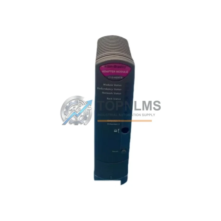
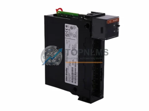
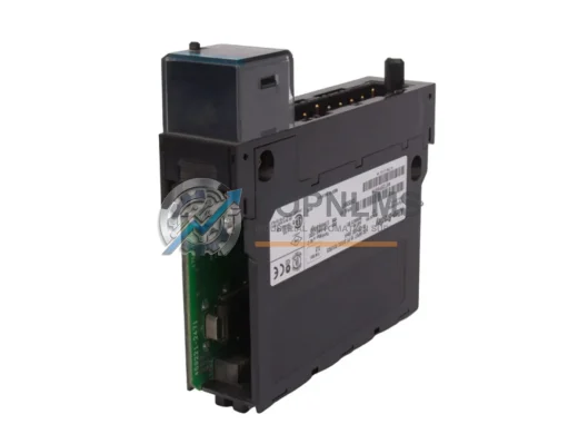
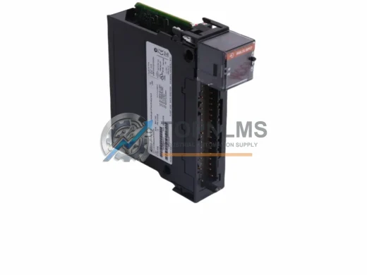
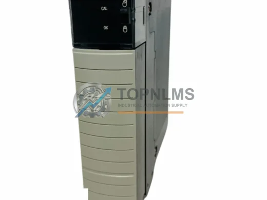
Allen-Bradley 1715-AENTR EtherNet/IP Adapter Upgrade: Seamless Transition for Redundant I/O Systems
The Allen-Bradley 1715-AENTR EtherNet/IP Adapter is the communication backbone of the 1715 Redundant I/O System — a platform engineered for high-availability process control environments where unplanned downtime is not an option. Whether you are replacing a failed unit, upgrading from an aging 1715-AENTR revision, or migrating an entire redundant I/O rack from a legacy ControlLogix or CompactLogix architecture, this adapter delivers the protocol compatibility, physical form factor, and firmware alignment your system demands.
The 1715 Redundant I/O platform is purpose-built for applications in oil and gas, chemical processing, power generation, and water treatment — industries where SIL-rated control loops and continuous process availability are non-negotiable. The 1715-AENTR serves as the EtherNet/IP interface between the redundant I/O chassis and the controller backplane, supporting dual-port EtherNet/IP topology (Device Level Ring, linear, and star) and enabling bumpless switchover between primary and secondary I/O paths.
When sourcing a replacement or upgrade unit, engineers frequently encounter compatibility questions around firmware revision matching, chassis slot assignment, and network topology reconfiguration. This guide addresses those concerns directly and outlines the migration path from legacy or discontinued adapter revisions to a verified, tested 1715-AENTR unit.
Compatibility Comparison Table
| Parameter |
Legacy / Outgoing Unit |
1715-AENTR (Replacement) |
| Model / SKU |
1715-AENTR (earlier revision) / discontinued adapter variants |
1715-AENTR (current production revision) |
| Communication Protocol |
EtherNet/IP (CIP) |
EtherNet/IP (CIP) — fully compatible |
| Network Topology Support |
Linear / Star |
DLR (Device Level Ring), Linear, Star |
| Dual-Port Ethernet |
Varies by revision |
Yes — dual RJ-45 ports standard |
| Chassis Compatibility |
1715-A2A / 1715-A3IO chassis |
1715-A2A / 1715-A3IO — direct fit |
| Controller Compatibility |
ControlLogix L7x / L8x series |
ControlLogix L7x / L8x / L9x — expanded support |
| Redundancy Mode |
Primary / Secondary I/O path |
Primary / Secondary — bumpless switchover retained |
| Power Supply Requirement |
24 VDC from 1715-PS4 or equivalent |
24 VDC — same power rail, no rewiring required |
| Installation Footprint |
Single slot, 1715 chassis |
Single slot — identical physical dimensions |
| Firmware Update Required |
Depends on source revision |
Recommended — align with Studio 5000 project revision |
| Wiring Changes Required |
None — Ethernet patch cables reuse existing runs |
| Warranty |
— |
12-Month Warranty from TOPNLMS |
Seamless Upgrade Solutions
A successful 1715-AENTR migration rarely involves a single component swap. In practice, field engineers replacing or upgrading the EtherNet/IP adapter must also verify the condition and compatibility of adjacent modules within the same redundant I/O chassis and the broader ControlLogix control system. The following components are commonly addressed during the same maintenance window or upgrade project.
The 1715-A3IO I/O chassis and 1715-A2A adapter chassis form the physical housing for the 1715-AENTR. If the chassis backplane has sustained damage or corrosion — common in high-humidity process environments — replacing the adapter alone will not restore system integrity. Inspecting and, where necessary, replacing the chassis alongside the adapter is standard practice.
On the I/O side, the 1715-IB16D digital input module and 1715-OB8DE digital output module are the most frequently paired modules in 1715 Redundant I/O builds. These modules communicate through the adapter to the ControlLogix controller, and their firmware revisions must be compatible with the adapter’s EDS file version registered in Studio 5000 Logix Designer. During a migration, engineers should export the existing I/O configuration, verify module revision alignment, and re-import after the adapter swap.
Power integrity is equally critical. The 1715-PS4 power supply module provides the 24 VDC rail that feeds the 1715-AENTR and associated I/O modules. If the power supply is approaching end-of-life or showing voltage ripple, replacing it concurrently with the adapter eliminates a second maintenance window and reduces cumulative downtime risk.
At the controller level, the 1756-EN2TR EtherNet/IP communication module installed in the ControlLogix chassis is the upstream network peer of the 1715-AENTR. Ensuring the 1756-EN2TR firmware is current and that the DLR ring configuration is correctly defined in the controller project is a prerequisite for stable adapter operation post-replacement. In redundant controller configurations using the 1756-RM2 redundancy module, the switchover behavior of the 1715-AENTR must be validated against the redundancy synchronization settings to confirm bumpless I/O transfer is preserved.
For sites migrating from older 1715 system builds that used legacy programming cables or serial-based configuration tools, the transition to EtherNet/IP-native configuration via the 1756-ENBT or 1756-EN2T communication bridge is a common parallel task. These modules enable the engineering workstation running Studio 5000 to reach the 1715-AENTR for firmware updates and online diagnostics without requiring a dedicated serial connection.
Finally, in installations where signal isolation between field devices and the control system is required — particularly in hazardous area classifications — signal isolators and Zener barriers installed upstream of the 1715 I/O modules must be verified for compatibility with the updated I/O module firmware. This is especially relevant when upgrading from early-revision 1715 builds where analog input modules such as the 1715-IF16 may have had different scaling or filtering behavior.
Retrofit Guidance FAQ
Q: Do I need to rewire the Ethernet connections when replacing the 1715-AENTR?
No. The 1715-AENTR uses standard RJ-45 Ethernet connectors. Existing Cat5e or Cat6 patch cables connecting the adapter to the plant network switch or DLR ring can be reused without modification. Verify cable condition and connector seating before powering up the replacement unit.
Q: Will my existing Studio 5000 project work with the replacement adapter?
In most cases, yes — provided the replacement unit’s firmware revision is compatible with the EDS file version referenced in your project. If the firmware revision differs, update the adapter firmware using ControlFLASH or ControlFLASH Plus before going online. Always perform a firmware update with the I/O chassis de-energized from the process where possible.
Q: Does replacing the 1715-AENTR require changes to the EtherNet/IP network topology configuration?
No topology reconfiguration is required if the replacement unit is installed in the same chassis slot and assigned the same IP address as the outgoing unit. The DLR ring supervisor settings and port configurations are stored in the controller project, not in the adapter itself, so they are preserved across the swap.
Q: How do I verify that the redundant I/O switchover is functioning correctly after the replacement?
After installing the replacement 1715-AENTR and bringing the system online, use the RSLinx Classic or Studio 5000 online diagnostics to confirm both the primary and secondary I/O paths are active and synchronized. Initiate a manual switchover test (if process conditions permit) to validate bumpless transfer. Review the controller’s fault log for any I/O connection errors before returning the system to automatic operation.
Q: What physical space is required for installation?
The 1715-AENTR occupies a single slot in the 1715-A2A adapter chassis. No additional panel space or DIN rail mounting is required. The module’s depth and connector clearance are identical across revisions, so existing cable management and enclosure layouts are unaffected.
Q: Can the 1715-AENTR be used in a non-redundant I/O configuration?
The 1715 platform is designed exclusively for redundant I/O applications. The 1715-AENTR is not intended for use as a standard EtherNet/IP adapter in non-redundant 1734 POINT I/O or 1756 ControlLogix I/O configurations. For non-redundant EtherNet/IP I/O, consider the 1734-AENTR (POINT I/O) or 1756-EN2TR (ControlLogix backplane communication).
Warranty Assurance
Every 1715-AENTR unit shipped by TOPNLMS is covered by a 12-month warranty from the date of delivery. Prior to shipment, each unit undergoes functional verification including power-on self-test, Ethernet port continuity check, and firmware revision confirmation. Units are packaged in anti-static ESD bags with protective foam inserts to prevent transit damage.
If a unit develops a fault within the warranty period under normal operating conditions, TOPNLMS will provide a replacement unit or issue a full refund — whichever the customer prefers. Our technical support team is available to assist with installation questions, firmware compatibility queries, and post-installation diagnostics. Response time for warranty claims is typically within 1 business day.
Stock is maintained in our Xiamen warehouse for immediate dispatch. Standard international shipping lead time is 3–7 business days depending on destination. Express courier options (DHL, FedEx) are available for urgent replacement requirements. A certificate of conformance and packing list are included with every shipment.
For procurement inquiries, bulk pricing, or technical pre-sales support, contact our team directly:
- Email: [email protected]
- Phone / WhatsApp: +86 18359293191
- Website: https://topnlms.com
© 2026 TOPNLMS. All rights reserved. Original Source: https://topnlms.com | Contact: [email protected] | +86 18359293191