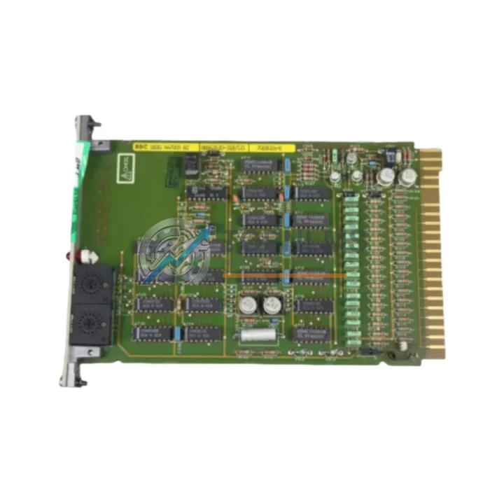
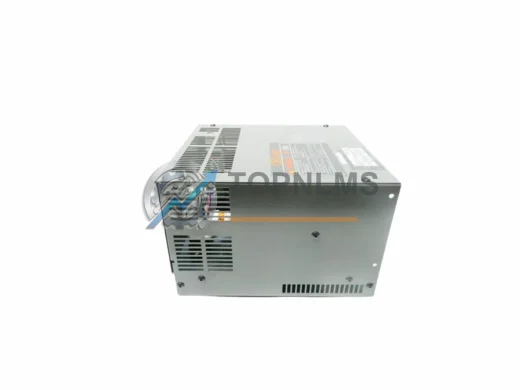
Product Overview
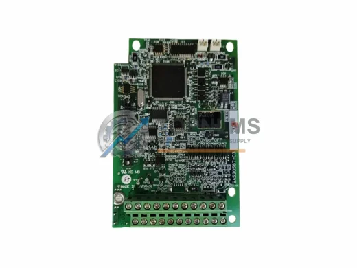
FUJI Electric RREG0A Original Industrial Spare FRENIC Compatible
The FUJI Electric RREG0A is a genuine regenerative braking unit engineered for FRENIC series variable frequency drive (VFD) systems. In industrial environments where motor-driven loads demand precise deceleration control — overhead cranes, hoists, centrifuges, compressors, and high-inertia conveyor lines — the RREG0A plays a critical role in returning braking energy back to the supply network rather than dissipating it as heat. Maintaining a verified spare of this unit is a cornerstone of any responsible preventive maintenance program for FUJI Electric drive systems.
Whether your facility operates a single FRENIC-Multi, FRENIC-Ace, or FRENIC-MEGA drive, or manages a fleet of drives across multiple production lines, the RREG0A is the factory-specified regenerative braking solution that ensures system stability, reduces thermal stress on the drive cabinet, and extends the operational lifespan of the entire drive assembly. Sourcing a tested, original spare before a failure event is the most cost-effective strategy available to maintenance engineers managing aging FUJI Electric installations.
Critical Technical Specs Table
| Parameter |
Specification |
| Model / SKU |
RREG0A |
| Brand |
FUJI Electric |
| Series Compatibility |
FRENIC-Multi, FRENIC-Ace, FRENIC-MEGA, FRENIC-HVAC |
| Unit Type |
Regenerative Braking Unit (RBU) |
| Function |
Returns braking energy to AC supply; eliminates need for braking resistor in regenerative loads |
| Input Voltage |
3-phase 200–240V AC / 380–480V AC (series-dependent) |
| Mounting |
DIN rail / panel mount, compatible with FRENIC drive cabinet footprint |
| Communication |
Integrated with FRENIC drive control bus; no additional wiring adapter required |
| Country of Origin |
Japan |
| Weight |
2.3 kg |
| Condition |
Original, new or tested-good surplus |
| Pre-shipment Test |
Full functional and insulation test performed before dispatch |
| Warranty |
12 Months from date of shipment |
| Shipping |
Worldwide express; ships from Xiamen within 1–3 business days |
Preventive Maintenance Strategy
A regenerative braking unit does not operate in isolation. The RREG0A interfaces directly with the FRENIC drive’s DC bus and the upstream power supply network, meaning its health is interdependent with several other components in the same control cabinet. A structured preventive maintenance inspection should treat the RREG0A as part of a broader system check.
When scheduling a planned shutdown to inspect or replace the RREG0A, maintenance teams should simultaneously verify the condition of the FRENIC drive’s main control board — models such as the FRENIC-Mega control PCB or the FRENIC-Ace keypad/operator panel are common wear items that benefit from proactive replacement during the same maintenance window. The drive’s input reactor and output filter capacitors should also be inspected, as degraded capacitors accelerate stress on the braking circuit.
Within the same cabinet, the 24VDC power supply module feeding the PLC or relay logic should be tested for output stability. A failing power supply can cause erratic braking commands that prematurely stress the RREG0A. Similarly, the I/O terminal block assemblies and signal wiring connecting the drive’s fault relay outputs to the plant SCADA or DCS should be inspected for loose terminations and insulation degradation.
For facilities running FUJI Electric FRENIC drives alongside a Micrex-SX or Micrex-F series PLC, the communication module linking the drive to the controller — typically a PROFIBUS-DP or Modbus RTU interface card — should be confirmed as functional. A communication fault that prevents the PLC from issuing a controlled stop command forces the drive into emergency braking mode, placing abnormal load on the RREG0A.
Signal isolators installed between the drive’s analog speed reference input and the control system are another frequently overlooked maintenance item. Degraded isolation can introduce ground loops that corrupt speed reference signals, causing unintended acceleration and deceleration cycles that increase braking unit wear. Fuse modules protecting the drive’s control circuit power supply should be checked and a set of replacement fuses stocked alongside the RREG0A spare.
For high-availability production lines, maintaining a minimum inventory of one RREG0A unit, one FRENIC drive control board, and one set of input/output terminal blocks ensures that a complete drive section can be restored within a single shift, minimizing production loss during an unplanned failure event.
Strategic Replacement Solutions
The RREG0A is designed as a direct replacement for the factory-installed regenerative braking unit in compatible FRENIC series drives. No firmware modification or parameter re-entry is required for a like-for-like swap — the replacement unit is recognized automatically by the drive’s self-diagnostic routine upon power-up.
For facilities where the original RREG0A has reached end-of-life due to capacitor aging, IGBT degradation, or physical damage from a fault event, the replacement procedure is straightforward: isolate the drive from mains supply, discharge the DC bus to safe voltage levels (verify with a calibrated meter), disconnect the DC bus terminals and control signal connectors, remove the failed unit, install the RREG0A, and restore power. The drive’s fault history should be cleared and a no-load test run performed before returning the system to production.
For older FRENIC installations where the original braking unit model has been superseded, the RREG0A serves as the current production equivalent, maintaining full electrical and mechanical compatibility with the existing drive cabinet layout. This eliminates the need for cabinet modification, rewiring, or drive parameter migration — a significant advantage in facilities where engineering documentation for legacy systems is incomplete.
Facilities managing multiple FRENIC drives across different power ratings should note that the RREG0A is applicable across a defined kW range within the FRENIC product family. Confirming the drive’s rated output current against the RREG0A’s rated capacity before installation is the only verification step required. TOPNLMS technical support can assist with compatibility confirmation prior to order placement.
Support FAQ
Q1: How do I confirm the RREG0A is compatible with my specific FRENIC drive model?
Provide your FRENIC drive’s full model number (found on the nameplate) to our technical team at [email protected]. We will cross-reference the drive’s rated capacity and series designation against the RREG0A specification sheet and confirm compatibility before shipment.
Q2: What pre-shipment testing is performed on the RREG0A?
Every RREG0A unit undergoes a full functional test including DC bus charge/discharge cycle verification, IGBT gate drive signal integrity check, and insulation resistance measurement before packaging. A test report is available upon request.
Q3: What does the 12-month warranty cover?
The warranty covers all manufacturing defects and functional failures under normal operating conditions for 12 months from the date of shipment. In the event of a warranty claim, we provide a replacement unit or full refund after fault verification. Return shipping for confirmed warranty cases is covered by TOPNLMS.
Q4: Can I stock the RREG0A as a long-term spare without degradation?
Yes. Stored in original packaging in a dry, temperature-controlled environment (5–40°C, <85% RH non-condensing), the RREG0A can be held as a shelf spare for 3–5 years without performance degradation. We recommend an annual visual inspection and a brief power-on self-test if the unit has been stored for more than 24 months before installation.