Product Overview
FUJI Electric EP-3603D-C Replacement for FRENIC VFD: Seamless Transition & Legacy System Compatibility
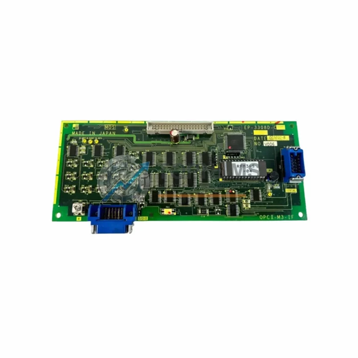
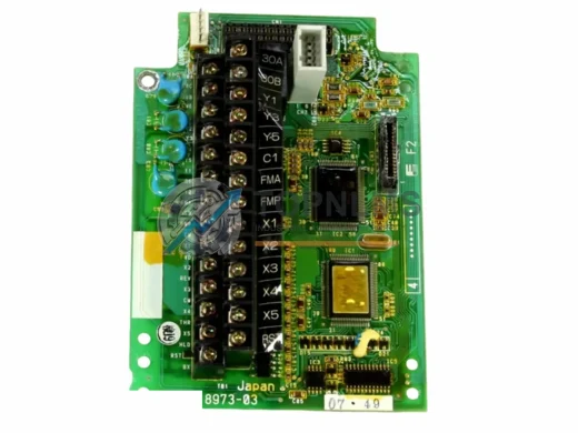
When your FUJI Electric FRENIC series variable frequency drive system signals a fault on the EP-3603D-C power drive board, every hour of unplanned downtime translates directly into production loss. Whether you are managing a legacy FRENIC5000 G11/P11 installation, a mid-generation FRENIC-Eco (FRN-F1) line, or a more recent FRENIC-MEGA (FRN-G1) rack, the EP-3603D-C is a critical gate-driver and power-stage interface board that governs IGBT switching, DC bus monitoring, and fault-signal routing between the control card and the power module stack.
TOPNLMS maintains verified stock of the EP-3603D-C and its functionally compatible successors, sourced directly from authorised distribution channels and subject to full incoming inspection before dispatch. Our engineering team has documented the board’s connector pinout, gate-resistor values, and optocoupler layout against the original FUJI Electric service schematics, enabling us to confirm compatibility before shipment and to support your on-site commissioning team remotely if required.
Compatibility Comparison Table
| Parameter |
Legacy / Outgoing |
EP-3603D-C (Current) |
Notes |
| Part Number |
EP-3603D-B / EP-3603C |
EP-3603D-C |
Direct form-fit-function replacement |
| Compatible Drive Series |
FRENIC5000 G11, P11 |
FRENIC-Eco, FRENIC-MEGA, FRENIC-HVAC |
Verify drive firmware revision before swap |
| Power Range |
11–75 kW (400 V class) |
11–90 kW (400 V class) |
Extended upper range on -C revision |
| Gate Drive Interface |
6-channel IGBT gate driver |
6-channel IGBT gate driver |
Pin-compatible; no rewiring required |
| DC Bus Voltage Sensing |
Resistor divider, ±2% |
Resistor divider, ±1.5% |
Improved accuracy on -C revision |
| Fault Signal Output |
Open-collector, 24 V |
Open-collector, 24 V |
Fully compatible with existing control wiring |
| Communication Protocol |
Internal parallel bus |
Internal parallel bus |
No protocol change; control card unchanged |
| Mounting / Rack Fit |
Standard FRENIC power-stage chassis |
Standard FRENIC power-stage chassis |
Same screw pattern and standoff height |
| Cooling Requirement |
Forced-air, internal fan |
Forced-air, internal fan |
No heatsink modification required |
| Replacement Recommendation |
Replace as a matched pair with the IGBT power module (6MBP75RA060 or equivalent) when cumulative run hours exceed 40,000 h |
Reduces repeat call-outs |
| Warranty |
— |
12 Months |
Covers manufacturing defects; DOA exchange within 7 days |
Seamless Upgrade Solutions
A drive board replacement rarely occurs in isolation. In practice, the EP-3603D-C swap is most successful when the surrounding subsystem is evaluated at the same time. During a FRENIC-Eco or FRENIC-MEGA retrofit, engineers commonly address the following components in the same maintenance window:
The FRENIC control PCB (CP-series) — typically the CP-3603D or CP-3604 — interfaces directly with the EP-3603D-C via the internal ribbon connector. If the control card shows parameter-loss faults or keypad communication errors alongside the drive board fault, replacing both boards simultaneously eliminates the risk of a second unplanned outage within weeks. Similarly, the FRENIC keypad / operator panel (TP-E1U or TP-G1) should be inspected; a corrupted parameter set caused by a drive board failure can persist in keypad memory and re-trigger faults after the board swap if the panel is not re-initialised.
On the power side, the IGBT power module — commonly a Mitsubishi CM75DU-24F or Fuji 6MBP75RA060 depending on the drive frame size — is the component most likely to have caused the EP-3603D-C failure in the first place. Overcurrent events that destroy the gate-driver board almost always leave latent damage in the IGBT junctions. Replacing the drive board without inspecting the power module is a leading cause of repeat failures within 30 days. TOPNLMS can supply matched IGBT modules alongside the EP-3603D-C to support a complete power-stage rebuild.
The DC bus capacitor bank is another age-sensitive component. In drives with more than 8 years of service, capacitor ESR rise is a common root cause of DC bus ripple that stresses the drive board’s voltage-sensing circuit. Capacitor replacement kits for the FRENIC-Eco 400 V / 75 kW frame are available and are recommended when the drive board is being replaced as part of a planned overhaul rather than an emergency repair.
For installations where the FRENIC drive communicates with a host PLC — such as a FUJI Electric MICREX-SX SPH series PLC or a third-party controller via Modbus RTU over RS-485 — the communication module (OPC-G1-RS or OPC-E2-RS) should be verified after the board swap. Drive board replacements can reset the RS-485 node address and baud-rate parameters to factory defaults, causing the PLC to lose communication with the drive until parameters are restored. Having the parameter backup file (saved via the TP-E1U keypad or FRENIC Loader PC software) on hand before the swap is strongly recommended.
Where the FRENIC drive is integrated into a larger MCC (Motor Control Centre) or control cabinet alongside contactors, circuit breakers, and a 24 V DC power supply module, the control-voltage rail should be checked for ripple before re-energising the drive. A degraded SMPS inside the cabinet can introduce noise that mimics drive board faults and leads to misdiagnosis. TOPNLMS also stocks 24 V DIN-rail power supplies compatible with standard IEC control cabinet layouts for customers undertaking a broader cabinet modernisation.
Finally, for sites migrating from an older FRENIC5000 G11 or P11 to a current-generation FRENIC-MEGA or FRENIC-HVAC platform, the EP-3603D-C is often the last original component remaining in an otherwise upgraded drive. In these hybrid configurations, confirming that the new control card firmware supports the -C revision drive board is essential — TOPNLMS provides pre-shipment firmware verification on request.
Retrofit Guidance FAQ
Q: Do I need to rewire the motor terminals when replacing the EP-3603D-C?
No. The EP-3603D-C is an internal drive board and does not connect directly to the motor terminals (U, V, W) or the mains input (R, S, T). All external wiring remains unchanged. Only the internal ribbon cable and gate-driver connectors are disturbed during the swap, and these are keyed to prevent incorrect reinsertion.
Q: Will my existing PLC program need modification after the board replacement?
No program changes are required. The EP-3603D-C replacement does not alter the drive’s external communication interface or I/O behaviour. However, drive parameters (acceleration ramp, frequency limits, motor nameplate data) must be restored from backup after the swap, as the replacement board ships with factory-default parameter values.
Q: Is the EP-3603D-C compatible with both Modbus RTU and PROFIBUS-DP communication options?
Yes. The drive board itself is protocol-agnostic; communication protocol is determined by the optional communication card (OPC-G1-PDP for PROFIBUS-DP, OPC-G1-RS for Modbus RTU) fitted to the control card slot. The EP-3603D-C replacement does not affect the communication card or its configuration.
Q: The replacement board arrived but the drive still shows an OC (overcurrent) fault. What should I check?
An OC fault after a drive board replacement most commonly indicates residual IGBT damage in the power module. Use a diode-mode multimeter test on the IGBT module before re-energising the drive. If the power module tests out of specification, contact TOPNLMS — we can supply the matched IGBT module and provide a step-by-step test procedure.
Q: How much physical space does the EP-3603D-C require inside the drive chassis?
The EP-3603D-C occupies the same footprint as the -B revision it replaces. No chassis modification, bracket relocation, or fan repositioning is required. The board mounts on four M4 standoffs and connects via two keyed ribbon cables.
Q: Can the EP-3603D-C be used in a drive that has been converted to a different voltage class?
No. The EP-3603D-C is rated for the 400 V (three-phase) drive class. Using it in a 200 V class drive will result in incorrect DC bus voltage sensing and potential gate-driver damage. Always confirm the drive nameplate voltage class before ordering.
Warranty Assurance
Every EP-3603D-C shipped by TOPNLMS is covered by a 12-month warranty against manufacturing defects, measured from the date of delivery. Our pre-shipment inspection process includes visual inspection for PCB damage, solder-joint integrity check under magnification, optocoupler function test, and gate-driver output verification on a calibrated test rig. Each board is individually serialised and the test record is retained for the warranty period.
In the event of a dead-on-arrival (DOA) situation — defined as a board that fails to restore drive operation when installed correctly in a confirmed-good drive chassis — TOPNLMS will dispatch a replacement unit within 24 hours of receiving photographic evidence of the fault and confirmation of the installation procedure followed. Return shipping of the DOA unit is arranged at our cost for orders within mainland China; international customers are provided with a prepaid return label.
For warranty claims arising during the 12-month coverage period, our after-sales response target is one business day for initial technical assessment and three business days for a resolution decision (repair, replacement, or credit). Customers with time-critical production environments are encouraged to discuss our advance-replacement programme, under which a replacement board is dispatched before the faulty unit is returned, subject to a refundable deposit.
Stock availability is confirmed at the time of order. For customers requiring multiple units for a planned maintenance programme or spare-parts inventory build, TOPNLMS offers volume pricing and staggered delivery scheduling. Lead time for in-stock units is typically 3–7 business days to most destinations in mainland China, with express options available for same-day dispatch on orders confirmed before 14:00 CST.
For procurement enquiries, technical pre-sales support, or warranty claims, contact our industrial automation team directly:
📧 [email protected]
📞 +86 18359293191