Product Overview
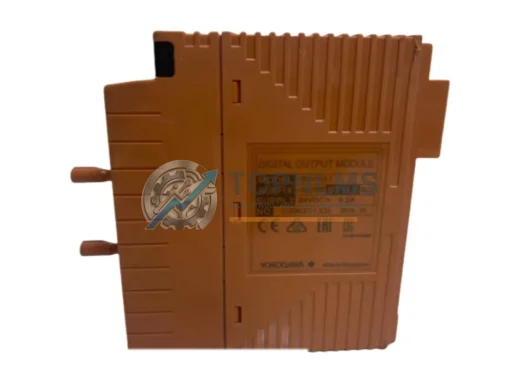
YOKOGAWA F3YP04-ON Original Industrial Spare FA-M3 Compatible: Ensuring System Stability in Demanding Automation Environments
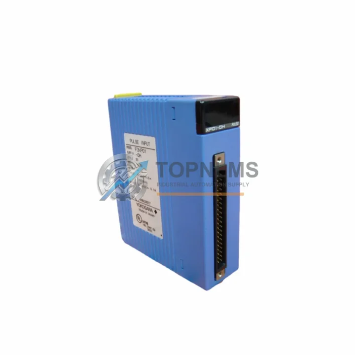
The YOKOGAWA F3YP04-ON is a genuine cam positioner module designed for the FA-M3 programmable controller platform — one of YOKOGAWA’s most widely deployed process and factory automation systems across petrochemical, power generation, pharmaceutical, and heavy manufacturing industries. As a critical I/O and positioning control component, the F3YP04-ON governs precise cam-based output sequencing, making it indispensable in applications where timing accuracy and output reliability directly affect production quality and equipment safety.
For maintenance engineers and procurement specialists managing aging FA-M3 control systems, securing a verified original F3YP04-ON spare is not merely a convenience — it is a risk management imperative. Unplanned downtime caused by a failed cam positioner module can cascade into line stoppages, safety interlock failures, and costly emergency procurement at premium prices. Stocking this module as part of a structured spare parts inventory strategy is the most effective way to protect operational continuity.
Critical Technical Specs
| Parameter |
Specification |
| Model / SKU |
F3YP04-ON |
| Brand |
YOKOGAWA |
| Series |
FA-M3 (FACTORY ACE) |
| Module Type |
Cam Positioner Output Module |
| Output Channels |
4 channels |
| Output Type |
Transistor output (NPN open collector) |
| Rated Voltage |
24 VDC |
| Max Load Current |
0.5 A per channel |
| Isolation |
Photocoupler isolation between I/O and internal bus |
| Mounting |
FA-M3 base unit slot (direct backplane mounting) |
| Compatible Base Units |
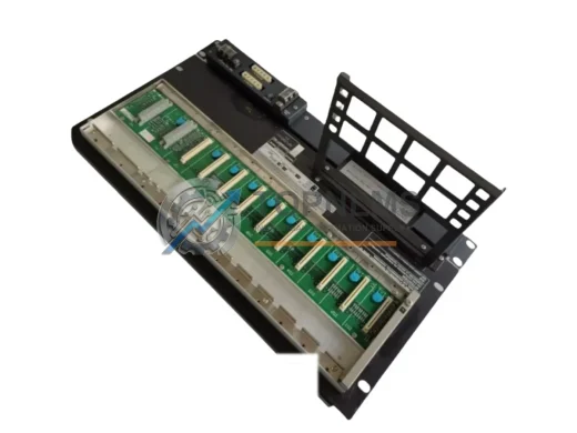
F3SP22-0S, F3SP28-3N, F3SP38-6N, F3SP53-4H, F3SP58-6H and compatible FA-M3 CPU bases |
| Operating Temperature |
0°C to 55°C |
| Storage Temperature |
-25°C to 70°C |
| Humidity |
10% to 90% RH (non-condensing) |
| Origin |
Japan |
| Weight |
Approx. 2,140 g (packaged) |
| Warranty |
12 Months from date of shipment |
| Condition |
Original, new or tested-good surplus |
Preventive Maintenance Strategy for FA-M3 Systems Incorporating F3YP04-ON
A cam positioner module failure rarely occurs in isolation. In FA-M3 control cabinets, the F3YP04-ON operates in close electrical and logical dependency with several adjacent modules and system components. A disciplined preventive maintenance program should treat the F3YP04-ON as part of a broader inspection and replacement cycle rather than a standalone unit.
During scheduled shutdowns or annual control cabinet inspections, maintenance teams should simultaneously evaluate the condition of the F3PU20-0S or F3PU16-0S CPU modules that execute the cam positioner logic. If the CPU module shows signs of firmware instability, memory errors, or communication timeouts, replacing it alongside the F3YP04-ON eliminates the risk of a secondary failure shortly after the primary repair. Similarly, the F3NC96-0N or F3NC32-0N network communication modules that relay positioning data to supervisory systems should be inspected for connector wear and communication error logs.
Power integrity is a leading cause of premature module failure. The F3PW01-0S or F3PW02-0S power supply modules feeding the FA-M3 base unit should be tested for output voltage stability and ripple under load. A degraded power supply can cause intermittent cam positioner faults that are misdiagnosed as module failures. Replacing the power supply module as a precautionary measure during the same maintenance window is a cost-effective strategy that prevents repeat callouts.
On the I/O side, the F3XD32-3N digital input modules that feed encoder or proximity sensor signals into the cam positioner logic should be checked for input filter drift and channel response time. Worn terminal blocks and loose wiring on these input modules are a common source of erratic cam output behavior. Pairing an F3YP04-ON replacement with a fresh set of F3TB32-0N terminal block assemblies ensures that the new module operates into a clean, low-resistance wiring interface from day one.
For systems where the FA-M3 controls servo or stepper-driven positioning axes, the F3YP14-0N or F3YP28-0N pulse output modules in the same cabinet should be inspected for output transistor degradation. These modules share the same backplane bus and power rail as the F3YP04-ON, and their failure modes are similar. Stocking one spare of each cam and pulse output module type is a recognized best practice in facilities with multiple FA-M3 racks.
Finally, the F3EM01-0N Ethernet communication module or equivalent fieldbus interface modules connecting the FA-M3 to SCADA or DCS layers should be verified for firmware version compatibility whenever a cam positioner module is replaced. Firmware mismatches between the CPU and I/O modules can cause initialization errors that delay restart after maintenance. Keeping a documented firmware matrix for all installed FA-M3 modules is a simple governance measure that significantly reduces post-maintenance commissioning time.
Strategic Replacement Solutions: Extending FA-M3 System Life with Original Spares
Many facilities operating FA-M3 systems installed in the 1990s and 2000s face a common challenge: YOKOGAWA has transitioned its primary support focus to newer platforms such as the STARDOM FCN/FCJ and the ProSafe-RS safety controller series. While FA-M3 hardware remains available through authorized channels and specialist distributors, lead times for certain modules have extended, and the risk of receiving non-original or refurbished units from unverified sources has increased.
Sourcing the F3YP04-ON from a verified specialist supplier like TOPNLMS provides a direct mitigation for this risk. Each unit offered is either new-in-box original stock or tested-good surplus that has passed functional verification against YOKOGAWA’s published electrical specifications. This approach allows facilities to maintain their existing FA-M3 infrastructure without the capital expenditure and re-engineering cost of a full platform migration — a project that typically requires 6–18 months of engineering effort and significant process downtime for cutover.
For sites managing multiple FA-M3 racks across different production lines, a consolidated spare parts procurement strategy — covering cam positioner modules, CPU units, power supplies, and communication modules in a single purchase order — reduces per-unit logistics costs and ensures that all critical spares arrive together, tested, and ready for immediate deployment. This approach also simplifies incoming inspection and documentation for ISO 9001 or IEC 62443 compliance purposes.
Support FAQ
Q1: Is the F3YP04-ON compatible with all FA-M3 base unit configurations?
The F3YP04-ON is designed for the YOKOGAWA FA-M3 (FACTORY ACE) platform and is compatible with standard FA-M3 base units that support transistor output modules. Compatibility depends on the specific CPU module and base unit revision installed in your system. We recommend confirming your base unit model number (e.g., F3BU04-0N, F3BU16-0N) before ordering. Our technical team can assist with compatibility verification based on your system configuration.
Q2: What pre-shipment testing is performed on each F3YP04-ON unit?
Each F3YP04-ON unit undergoes functional verification prior to shipment, including output channel continuity testing, isolation resistance measurement, and visual inspection for physical damage or component degradation. Units sourced as new-in-box original stock are shipped in original YOKOGAWA packaging with factory labels intact. Tested surplus units are accompanied by a test report confirming pass status against key electrical parameters.
Q3: What does the 12-month warranty cover, and how is a warranty claim processed?
The 12-month warranty covers manufacturing defects and functional failures under normal operating conditions as specified in YOKOGAWA’s FA-M3 installation guidelines. It does not cover damage resulting from incorrect installation, overvoltage events, or environmental conditions outside the rated operating range. To initiate a warranty claim, contact [email protected] with your order number, a description of the failure symptom, and photographic documentation. Replacement or repair will be arranged within 5 business days of claim verification.
Q4: How should the F3YP04-ON be stored if purchased as a strategic spare before it is needed?
For long-term storage, the F3YP04-ON should be kept in its original anti-static packaging in a climate-controlled environment at 15°C to 35°C with relative humidity below 70% (non-condensing). Avoid storage near strong magnetic fields, corrosive gases, or direct sunlight. Modules stored under these conditions retain full functionality for 3–5 years. For storage exceeding 2 years, we recommend a brief functional verification test before installation to confirm that electrolytic capacitors and output transistors remain within specification.