
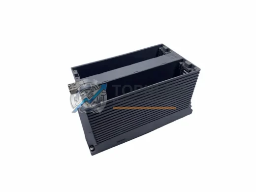
Yokogawa
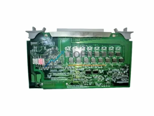
YOKOGAWA AMN32 S1 Original Industrial Spare CENTUM VP Compatible
AMN32 S1YOKOGAWA AMN32 S1 original DCS I/O module for CENTUM VP systems. Verified spare, 12-month warranty, fast global shipping. Reduce downtime now.
Request availability, condition, lead time and export shipping details for ANB10D-421.
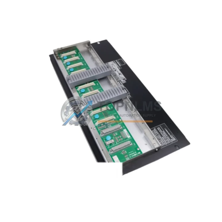
Send this exact part number, quantity and destination country. TOPNLMS will confirm availability, condition and export lead time before quotation.
In process-critical environments — refineries, chemical plants, power generation facilities, and continuous manufacturing lines — the reliability of every analog output channel directly determines whether your distributed control system maintains setpoint fidelity or triggers a costly process deviation. The Yokogawa ANB10D-421 is a 4-channel, 4–20 mA analog output module engineered for the CENTUM VP and CS 3000 DCS platforms. Sourced as an original Yokogawa spare, this module is the correct replacement for aging or failed ANB10D-series cards without requiring any firmware reconfiguration, I/O mapping changes, or engineering workstation intervention.
Unplanned downtime caused by a degraded analog output module is among the most disruptive failure modes in a DCS environment. A single channel drifting outside its calibrated range can cause a control valve to misposition, a flow controller to lose authority, or a safety interlock to receive a false signal. Maintaining a verified, tested ANB10D-421 in your on-site spare parts inventory is the most direct way to compress mean time to repair (MTTR) and protect production continuity.
| Parameter | Specification |
|---|---|
| Model / SKU | ANB10D-421 |
| Manufacturer | Yokogawa Electric Corporation |
| Compatible Platform | CENTUM VP, CS 3000 |
| Module Type | Analog Output (AO) |
| Number of Channels | 4 Channels |
| Output Signal Range | 4–20 mA DC |
| Resolution | 16-bit D/A conversion |
| Load Resistance | ≤ 600 Ω per channel |
| Isolation | Channel-to-channel and channel-to-bus isolation |
| Power Supply | Supplied via CENTUM VP node bus backplane |
| Mounting | Direct slot insertion into CENTUM VP / CS 3000 I/O nest |
| Operating Temperature | 0°C to 55°C |
| Humidity | 5% to 95% RH (non-condensing) |
| Country of Origin | Japan |
| Condition | Original, tested prior to shipment |
| Warranty | 12 Months from date of shipment |
A disciplined preventive maintenance program for a CENTUM VP or CS 3000 system extends well beyond replacing a single failed module. When scheduling a planned outage or conducting a control cabinet inspection that involves the ANB10D-421, experienced maintenance engineers treat the event as an opportunity to audit the health of the entire I/O nest and associated field wiring infrastructure.
Begin with the node bus backplane and I/O nest assembly: inspect connector pins for oxidation, verify that all module retention latches are fully engaged, and confirm that the nest power supply — typically a Yokogawa PW481 or equivalent CENTUM VP power module — is delivering stable voltage within specification. A marginal power supply is a common root cause of intermittent analog output errors that are misdiagnosed as module failures.
Inspect the field terminal unit (FTU) or marshalling cabinet terminal blocks connected to the ANB10D-421 output channels. Loose or corroded screw terminals on the FTU — such as the Yokogawa TB series terminal boards — can introduce resistance that shifts the effective 4–20 mA loop current and causes calibration drift at the final control element. Tighten all terminations and apply contact cleaner where corrosion is visible.
For each analog output channel, verify loop integrity by measuring the actual milliamp output at the field device with a calibrated loop calibrator. If any channel reads outside ±0.1% of the commanded value, the module should be replaced rather than recalibrated in place, as internal D/A converter degradation is typically progressive. Keep a Yokogawa ANB10D-421 and at least one ANB10S (single-channel AO variant, where applicable) in your critical spares kit to cover both standard and redundant output configurations.
While the cabinet is open, inspect adjacent analog input modules such as the Yokogawa AAI141 or AAI543 for similar signs of channel drift or LED fault indication. Analog input and output modules in the same I/O nest share environmental exposure and often exhibit correlated aging. Simultaneously audit any communication modules — including Yokogawa ACM12 or ESB bus coupler modules — for firmware version currency and connector integrity, as a communication fault can mask legitimate AO module alarms.
Do not overlook the field junction boxes and signal cable shielding between the marshalling cabinet and field instruments. Damaged cable shielding on 4–20 mA loops introduces noise that can cause the ANB10D-421 to output unstable signals even when the module itself is fully functional. Inspect and re-terminate shielding at a single grounding point per loop. Finally, verify that any signal isolators or loop-powered barriers in the circuit — such as Yokogawa-compatible galvanic isolators — are within their rated service life and have not developed internal leakage resistance.
The ANB10D-421 is a direct plug-and-play replacement for any failed or degraded ANB10D-series analog output card in a CENTUM VP or CS 3000 system. Because Yokogawa’s CENTUM platform maintains backward hardware compatibility across generations, the ANB10D-421 can be inserted into an existing I/O nest without modifying the system database, re-downloading control logic, or performing an engineering workstation reconfiguration. This makes it one of the most operationally efficient spare parts investments available for CENTUM-based facilities.
For sites still operating legacy CS 3000 systems, the ANB10D-421 provides a validated migration path that avoids the cost and risk of a full DCS upgrade. Rather than replacing an entire I/O nest or node controller to address a single failed output module, maintenance teams can restore full 4-channel analog output capability in under 15 minutes with a pre-tested replacement card. This approach preserves the existing control strategy, historian tags, and operator interface configurations — eliminating the engineering hours and validation burden associated with a system-level change.
For facilities managing multiple CENTUM VP nodes across a large plant, standardizing on a small buffer stock of ANB10D-421 modules — typically two to four units per node cluster — provides the inventory depth needed to respond to both random failures and scheduled turnaround replacements without relying on expedited international freight. Given typical lead times for original Yokogawa spare parts through distribution channels, maintaining on-site stock is the only reliable strategy for achieving same-shift restoration of failed analog output channels.
Q1: Is the ANB10D-421 compatible with both CENTUM VP and CS 3000 systems?
Yes. The ANB10D-421 is designed for Yokogawa’s CENTUM platform and is compatible with both CENTUM VP and CS 3000 I/O nest configurations. No hardware adapters or software changes are required for direct slot replacement.
Q2: What testing is performed before shipment?
Each ANB10D-421 unit is functionally tested prior to shipment to verify channel output accuracy, isolation integrity, and bus communication. A test record is available upon request. The module ships with a 12-month warranty covering manufacturing defects and functional failures under normal operating conditions.
Q3: How should I verify compatibility before installation?
Confirm that your I/O nest slot is designated for an AO module type in your CENTUM VP system database. Check the existing module label and the engineering workstation I/O builder to match the ANB10D suffix code (-421 denotes 4–20 mA output range). If you are replacing a module with a different suffix, contact our technical team before installation to confirm signal range compatibility with your field devices.
Q4: What is the recommended spare parts holding strategy for ANB10D-421?
For facilities with one to three CENTUM VP nodes, a minimum of two ANB10D-421 units is recommended. For larger installations with four or more nodes, a ratio of one spare per four installed modules is a practical baseline. Modules should be stored in anti-static packaging in a climate-controlled environment and rotated into service on a first-in, first-out basis to prevent storage-induced degradation of electrolytic components.
YOKOGAWA AMN32 S1 original DCS I/O module for CENTUM VP systems. Verified spare, 12-month warranty, fast global shipping. Reduce downtime now.
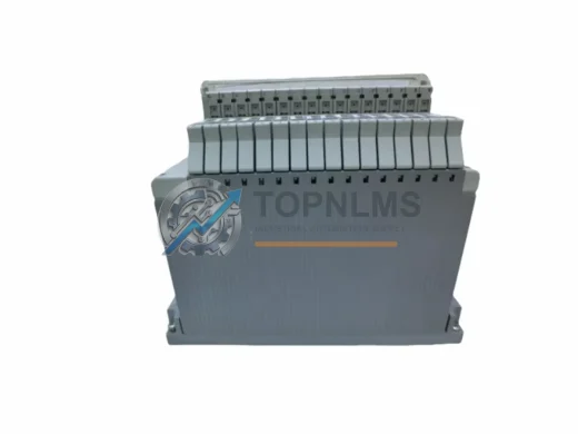
YOKOGAWA AMN21 replacement & upgrade solution for CENTUM CS3000/VP DCS. Compatible wiring, 12-month warranty, fast shipping. Contact: [email protected]
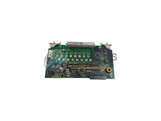
Yokogawa AMM12-S2 original analog input module for CENTUM DCS systems. Tested, 12-month warranty, fast worldwide shipping. Reduce downtime with genuine spares.
YOKOGAWA AMM21-S2 analog output module replacement for CENTUM VP DCS. Compatible upgrade solution. 12-month warranty. Fast global shipping from stock.
Click Quote This Model and the Part Number field will auto-fill with ANB10D-421.