
Siemens
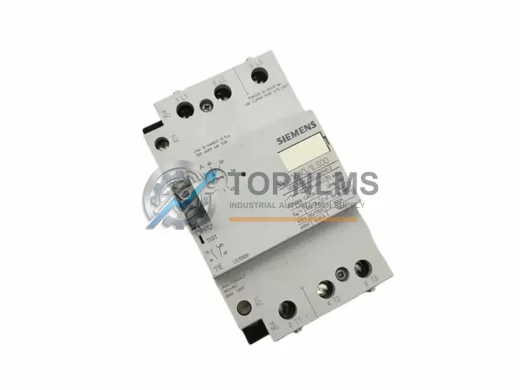
Siemens 3VU1640-1MJ00 Ruggedized Motor Protection Module
3VU1640-1MJ00Siemens 3VU1640-1MJ00 SIRIUS motor protection circuit breaker. Rugged, reliable, IEC-rated. In stock, tested, 12-month warranty. Fast global shipping.
Request availability, condition, lead time and export shipping details for 7SJ5115-5CA00-0A/HH.
Send this exact part number, quantity and destination country. TOPNLMS will confirm availability, condition and export lead time before quotation.
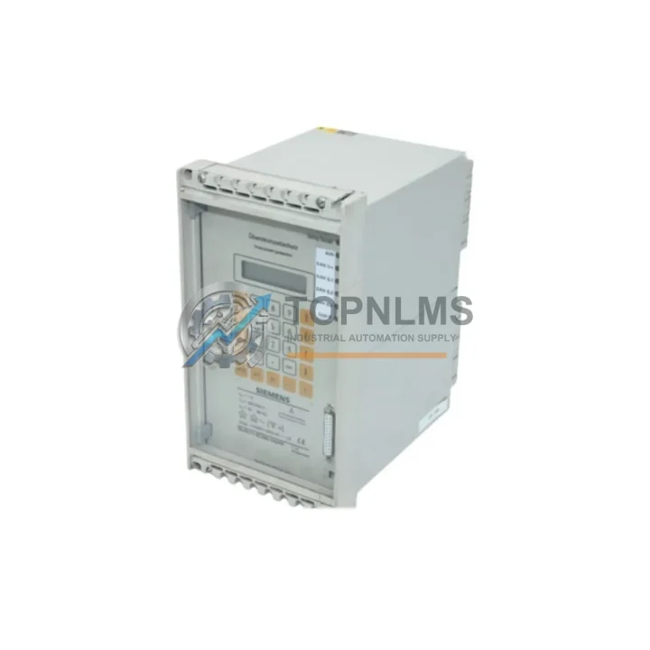
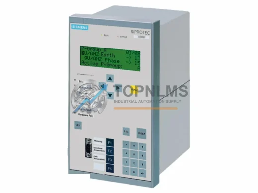
The Siemens 7SJ5115-5CA00-0A/HH is a SIPROTEC 4 series numerical overcurrent and earth-fault protection relay widely deployed in medium-voltage switchgear panels, industrial power distribution systems, and utility feeder protection applications. As aging SIPROTEC 4 installations approach end-of-service life or face discontinued spare-part availability, plant engineers and procurement teams are increasingly seeking verified replacement units that preserve existing wiring infrastructure, protection settings, and communication architecture — without requiring a full panel redesign or extended outage window.
This listing provides a tested, in-stock replacement unit for the 7SJ5115-5CA00-0A/HH, sourced to support direct swap-in scenarios where minimizing retrofit engineering time and downtime is the primary objective. Whether you are replacing a failed unit, building a critical spare inventory, or executing a phased modernization of an aging SIPROTEC 4 protection scheme, this relay is ready for immediate dispatch from our Xiamen warehouse.
| Parameter | Legacy / Outgoing Model | 7SJ5115-5CA00-0A/HH (This Unit) |
|---|---|---|
| Product Family | SIPROTEC 3 / Early SIPROTEC 4 | SIPROTEC 4 — 7SJ51 Series |
| Protection Function | Overcurrent (ANSI 50/51), Earth-Fault (ANSI 50N/51N) | Overcurrent (ANSI 50/51/51N) + Earth-Fault (ANSI 50N/51N/67N) |
| Rated Current Input | 1 A / 5 A (model-dependent) | 1 A / 5 A selectable |
| Auxiliary Voltage | 24–250 V DC / 115–230 V AC | 24–250 V DC / 115–230 V AC (wide-range) |
| Communication Interface | PROFIBUS DP / IEC 60870-5-103 | IEC 60870-5-103 / PROFIBUS DP / IEC 61850 (optional) |
| Mounting Format | Flush panel / rack 19″ | Flush panel / rack 19″ — same footprint |
| Wiring Compatibility | Screw-terminal rear connector | Screw-terminal rear connector — direct re-use |
| Configuration Tool | DIGSI 3 / DIGSI 4 | DIGSI 4 (v4.70+) |
| Replacement Recommendation | Direct swap with DIGSI 4 parameter re-upload | ✔ Confirmed compatible |
| Warranty | — | 12-Month Warranty (TOPNLMS) |
A successful migration from an aging SIPROTEC 3 or early SIPROTEC 4 installation to the 7SJ5115-5CA00-0A/HH typically involves more than a single relay swap. In practice, field engineers coordinate the replacement of several interdependent components to ensure the protection scheme remains coherent and the control cabinet layout is preserved.
The most common starting point is the DIGSI 4 programming cable (USB-to-RS232 or optical interface adapter), which is required to upload existing protection parameters from a DIGSI 4 project file into the replacement relay. If the original parameter file is unavailable, settings can be reconstructed from the relay’s front-panel display or from the substation’s protection coordination study documentation.
In installations where the 7SJ5115-5CA00-0A/HH is mounted in a SIPROTEC 4 rack alongside other protection devices — such as the 7SJ5511 feeder protection relay or the 7UT613 transformer differential relay — the system bus wiring (IEC 60870-5-103 or PROFIBUS DP segment) must be verified for address conflicts before the replacement unit is commissioned. The 7XV5650 SIPROTEC communication module or an equivalent IEC 61850 gateway may also need firmware alignment if the substation automation system has been upgraded since the original installation.
For installations that include a 6MD663 or 6MD664 bay control unit coordinating the protection relay outputs with the switchgear interlocking logic, the binary input/output mapping in the replacement relay must be verified against the existing CFC (Continuous Function Chart) logic blocks. This is particularly important where the relay’s trip output contacts drive the 3AH vacuum circuit breaker or a 3WL air circuit breaker shunt trip coil, as contact rating and trip pulse duration settings are safety-critical parameters.
Where the original installation used a 7SJ5115 with an analog measurement output card feeding a SICAM PAS or third-party SCADA historian, the replacement unit’s analog output configuration should be validated against the existing 4–20 mA loop wiring before energization. In some retrofit scenarios, a 7XV5100 signal converter or an equivalent signal isolator is inserted between the relay and the SCADA marshalling cabinet to resolve ground loop issues introduced during the panel refurbishment.
Finally, for sites where the protection relay is co-located with a SIMATIC S7-300 or S7-400 PLC performing supervisory interlocking, the PROFIBUS DP GSD file for the replacement 7SJ5115-5CA00-0A/HH should be re-imported into STEP 7 or TIA Portal to confirm that the data block structure and diagnostic telegram format match the existing PLC program expectations. This step prevents nuisance fault alarms during the first energization after relay replacement.
Q: Can I reuse the existing rear-terminal wiring when replacing with the 7SJ5115-5CA00-0A/HH?
A: Yes. The 7SJ51 series uses a standardized screw-terminal rear connector block. In most SIPROTEC 4 panel installations, the existing CT secondary wiring, VT wiring, binary input/output cables, and auxiliary power supply connections can be transferred directly to the replacement unit without re-termination, provided the terminal assignment matches the original relay’s wiring diagram. Always verify against the as-built panel drawing before energization.
Q: Do I need to reprogram the relay from scratch?
A: No. If a DIGSI 4 project file (.d4p) exists for the original relay, the protection parameters, setting groups, CFC logic, and communication configuration can be uploaded to the replacement unit via DIGSI 4 (v4.70 or later) in under 30 minutes. If the project file is unavailable, settings can be manually re-entered from the relay’s printed setting record or the protection coordination study.
Q: Is the 7SJ5115-5CA00-0A/HH compatible with IEC 61850 SCADA systems?
A: The base 7SJ5115 supports IEC 60870-5-103 and PROFIBUS DP natively. IEC 61850 Edition 1 communication is available as an optional hardware/firmware configuration (suffix dependent). If your substation automation system requires IEC 61850 GOOSE messaging or MMS reporting, confirm the relay’s order suffix includes the IEC 61850 communication module before installation.
Q: What is the physical panel cutout size, and will it fit my existing switchgear door?
A: The 7SJ51 series uses a standard 1/3 × 19″ (or equivalent flush-mount) panel cutout. The relay housing dimensions are compatible with existing SIPROTEC 4 panel cutouts, so no mechanical modification to the switchgear door or relay rack is required for a direct replacement.
Q: How long does commissioning typically take for a direct swap?
A: For a prepared replacement with an existing DIGSI 4 project file, experienced protection engineers typically complete the physical swap, parameter upload, functional test (trip test, binary I/O check, communication verification), and return-to-service within a 4–8 hour planned outage window. First-time installations without an existing project file may require an additional 4–8 hours for parameter reconstruction and protection coordination verification.
Every 7SJ5115-5CA00-0A/HH unit shipped by TOPNLMS is covered by a 12-month warranty from the date of delivery. Prior to dispatch, each unit undergoes a pre-shipment functional inspection that verifies power-up behavior, front-panel display operation, communication port response, and binary I/O continuity. Units that do not pass inspection are quarantined and not offered for sale.
In the event of a warranty claim, TOPNLMS provides a replacement unit or full refund within the warranty period. Our after-sales response target is 24 hours for initial acknowledgment and 72 hours for resolution proposal. Warranty claims are processed via email at [email protected] with the order number, unit serial number, and a brief fault description.
For procurement teams requiring documentation, we can provide a test report, packing list, and commercial invoice upon request. Export packing is reinforced for international air and sea freight, with ESD-safe inner packaging for all relay units. Lead time for in-stock units is typically 3–5 business days to most destinations.
For volume orders, framework agreements, or emergency same-day dispatch inquiries, contact our technical sales team directly.
Siemens 3VU1640-1MJ00 SIRIUS motor protection circuit breaker. Rugged, reliable, IEC-rated. In stock, tested, 12-month warranty. Fast global shipping.
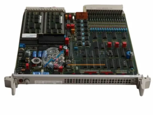
Siemens 7UT5121-4CB01-0AA0/LL SIPROTEC 4 differential protection relay. Compatible replacement & upgrade solution. 12-month warranty. Fast global shipping.
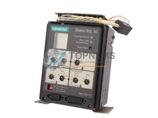
Siemens RMS-TSIG-TZ-C ruggedized electronic trip unit with zone-selective interlock for SENTRON 3WL ACBs. 12-month warranty. In stock. Fast global shipping.
Siemens 7UT6125-5EB20-1AA0/BB drop-in upgrade for SIPROTEC 7UT612. IEC 61850, PROFIBUS DP compatible. CT wiring reuse, 12-month warranty. Fast global shipping.
Click Quote This Model and the Part Number field will auto-fill with 7SJ5115-5CA00-0A/HH.