Product Overview
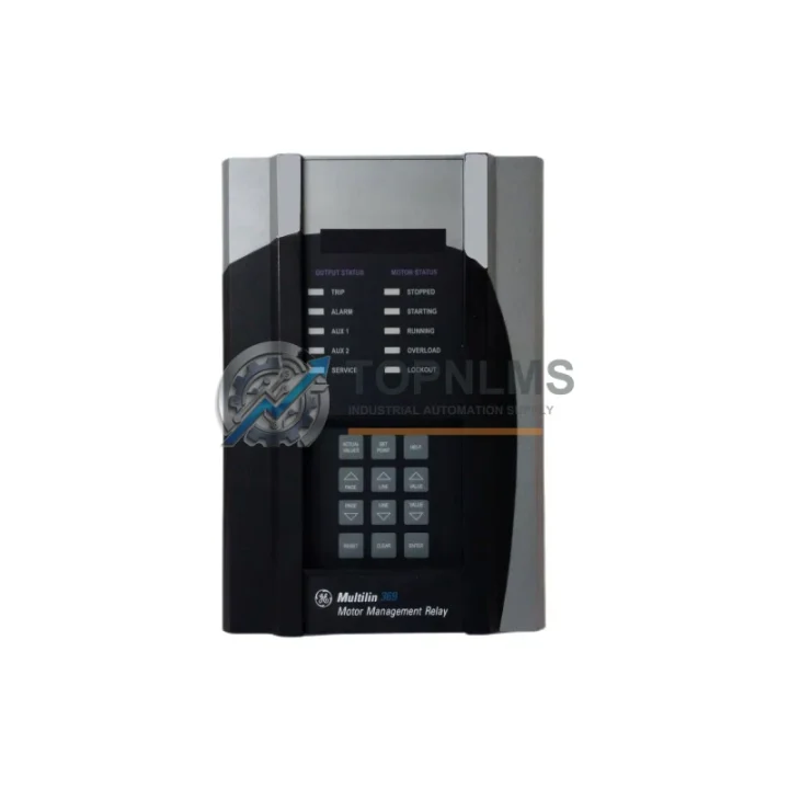
GE Multilin 369-HI-R-M-0-0-H-E Replacement for 369 Series: Seamless Transition & Legacy System Compatibility
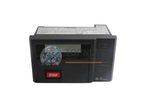
The GE Multilin 369-HI-R-M-0-0-H-E is a high-specification Motor Management Relay from the renowned GE Multilin 369 Series, engineered for comprehensive protection of medium-voltage and low-voltage AC motors in industrial environments. As the original 369-HI-R-M-0-0-H-E reaches end-of-life or becomes increasingly difficult to source, plant engineers and procurement teams face the critical challenge of maintaining motor protection continuity without triggering a full control system redesign. This replacement solution is purpose-built to address that challenge — delivering a smooth, low-risk migration path that preserves existing wiring infrastructure, communication architecture, and panel layout.
Whether your facility is operating aging GE Multilin 369 Series relays in motor control centers (MCCs), switchgear panels, or standalone motor feeder applications, this replacement unit maintains full functional parity with the original 369-HI-R-M-0-0-H-E. The relay supports the same terminal block pinout configuration, enabling direct wiring reuse without re-termination in most installations. Engineers familiar with the 369 Series parameter structure will find the configuration interface consistent, significantly reducing commissioning time and the risk of programming errors during cutover.
In distributed control system (DCS) environments where the 369-HI-R-M-0-0-H-E communicates upstream to a GE Mark VI, GE Fanuc Series 90, or third-party SCADA platform via Modbus RTU or DNP3, this replacement unit maintains identical protocol support. The RS-485 communication port configuration, baud rate settings, and register map remain compatible, allowing existing HMI screens — such as those built on GE iFIX, Wonderware, or Ignition — to continue polling motor status, trip logs, and energy data without modification to the communication driver or tag database.
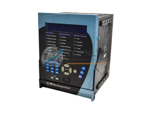
For facilities running GE Multilin SR Series protection relays alongside the 369, such as the SR469 Motor Management Relay or the SR750 Feeder Protection Relay, this 369-HI-R-M-0-0-H-E replacement integrates naturally into the same protection coordination scheme. Trip curves, CT ratios, and interlock logic configured in the existing relay coordination study remain applicable, minimizing the engineering effort required for protection re-coordination after replacement.
Physical installation compatibility is a key advantage of this replacement. The 369-HI-R-M-0-0-H-E occupies a standard panel cutout footprint consistent with the 369 Series form factor. In retrofit scenarios where the original relay is mounted in a GE PowerVac switchgear cabinet, a Siemens NXAIR panel, or a custom-built MCC bucket, the replacement unit fits within the existing DIN rail or panel-mount arrangement without requiring structural modification to the enclosure. This is particularly valuable in offshore, mining, and petrochemical installations where panel space is constrained and downtime windows are measured in hours.
Compatibility Comparison Table
| Parameter |
Original 369-HI-R-M-0-0-H-E |
Replacement Unit |
| Series |
GE Multilin 369 Series |
GE Multilin 369 Series (Compatible) |
| Protection Functions |
Overload, Undercurrent, Phase Unbalance, Ground Fault, Thermistor, RTD |
Full parity — all protection functions retained |
| Communication Protocol |
Modbus RTU (RS-485), DNP3 |
Modbus RTU (RS-485), DNP3 — register map compatible |
| Terminal Wiring |
Standard 369 Series terminal block layout |
Direct wiring reuse — no re-termination required in most cases |
| Panel Cutout / Mounting |
369 Series standard form factor |
Same footprint — DIN rail and panel-mount compatible |
| CT Input Range |
1A / 5A secondary CT inputs |
1A / 5A secondary CT inputs — fully compatible |
| RTD / Thermistor Inputs |
Up to 12 RTD inputs (model dependent) |
RTD and thermistor input configuration retained |
| Power Supply |
Hi-range auxiliary power (H variant) |
Hi-range auxiliary power — same supply voltage range |
| Output Relays |
Multiple configurable output relays |
Output relay configuration and wiring compatible |
| Replacement Recommendation |
— |
Direct drop-in replacement; verify firmware version for advanced features |
| Warranty |
— |
12-Month Warranty from shipment date |
Seamless Upgrade Solutions
A successful 369-HI-R-M-0-0-H-E replacement rarely involves the relay alone. In practice, the migration process touches several adjacent components within the motor protection and control circuit. During the replacement of the 369 Series relay, it is common to simultaneously address the condition of the GE Multilin 369 Series programming cable (EIA-232 to RS-485 converter) used for relay configuration via EnerVista 369 Setup software — older cables are frequently the source of communication faults that are misattributed to the relay itself.
In MCC applications, the GE Multilin 750/760 Feeder Protection Relay often operates in the same switchgear lineup as the 369, providing upstream feeder protection and coordinating trip signals with the motor relay. Verifying the interlock wiring between the 369 replacement and the 750/760 during commissioning ensures that the protection coordination scheme remains intact after cutover.
For installations where the 369-HI-R-M-0-0-H-E monitors motor temperature via RTD inputs, the associated RTD terminal modules and signal isolators in the wiring circuit should be inspected and replaced if degraded. Faulty RTD signal conditioning components are a common cause of nuisance thermal trips after relay replacement, and addressing them during the same maintenance window eliminates a second outage.
Where the motor is controlled via a GE Fanuc Series 90-30 PLC or a GE PACSystems RX3i controller, the discrete I/O wiring from the 369 relay’s output contacts to the PLC input module should be verified against the original wiring diagram. The IC693MDL645 or IC694MDL645 discrete input modules commonly used in these controllers accept the dry contact outputs from the 369 Series relay without modification, but terminal labeling should be confirmed during the replacement to prevent miswiring.
In facilities where the 369 relay communicates over an RS-485 Modbus network shared with other devices — such as a GE Multilin 469 Motor Management Relay protecting a larger motor, or a GE Multilin 239 Motor Protection Relay on a smaller feeder — the network termination resistor and biasing configuration should be verified after the replacement unit is installed. Incorrect termination is a frequent cause of intermittent communication faults on multi-drop RS-485 networks following any device substitution.
Finally, for sites upgrading from the 369 to a more modern protection platform, the GE Multilin 869 Motor Protection Relay represents the current-generation successor with expanded IEC 61850 GOOSE messaging capability, enhanced power quality metering, and a wider auxiliary power supply range. The 869 shares conceptual similarities with the 369 Series protection philosophy, making it a logical long-term upgrade target for facilities planning a phased modernization of their motor protection infrastructure.
Retrofit Guidance FAQ
Q: Can I reuse the existing CT wiring when replacing the 369-HI-R-M-0-0-H-E?
A: Yes. The replacement unit accepts the same 1A and 5A secondary CT inputs as the original 369-HI-R-M-0-0-H-E. In most installations, the CT secondary wiring can be transferred directly to the replacement relay terminals without modification, provided the terminal block layout is verified against the replacement unit’s wiring diagram before energization.
Q: Will my existing Modbus RTU communication configuration work with the replacement relay?
A: The replacement unit supports Modbus RTU over RS-485 with a register map compatible with the original 369 Series. Existing SCADA or DCS communication drivers, polling addresses, and tag mappings should function without modification. It is recommended to verify the slave address and baud rate settings in the replacement relay match those of the original unit before reconnecting the communication cable.
Q: Does the replacement unit fit in the same panel cutout as the original 369-HI-R-M-0-0-H-E?
A: Yes. The replacement unit conforms to the standard 369 Series panel mounting dimensions. No panel cutout modification is required for standard installations. DIN rail mounting hardware from the original installation can typically be reused.
Q: How do I transfer the protection settings from the failed relay to the replacement unit?
A: If a backup of the original relay settings was saved using GE’s EnerVista 369 Setup software, the settings file can be uploaded directly to the replacement unit via the RS-232 programming port. If no backup exists, settings should be re-entered manually based on the motor protection coordination study or the original commissioning documentation.
Q: What is the auxiliary power supply voltage range for the 369-HI-R-M-0-0-H-E (H variant)?
A: The “H” designation in the model number indicates a Hi-range auxiliary power supply, typically rated for 110–240V AC/DC. The replacement unit supports the same Hi-range supply voltage, ensuring compatibility with the existing panel power distribution without requiring a separate power supply or transformer.
Q: Can the replacement relay be used in a hazardous area (Ex) installation?
A: The 369 Series relay itself is typically installed in a safe area panel or MCC, with field wiring routed to motors in classified areas via appropriate barriers or isolators. The replacement unit does not alter this architecture. Consult the site’s area classification drawings and the relay’s installation manual to confirm barrier and isolator requirements remain unchanged.
Warranty Assurance
Every 369-HI-R-M-0-0-H-E replacement unit supplied by TOPNLMS is backed by a 12-month warranty from the date of shipment. Prior to dispatch, each unit undergoes functional testing to verify protection function operation, communication port integrity, output relay continuity, and auxiliary power supply performance. Units that do not meet specification are quarantined and not shipped.
In the event of a warranty claim, TOPNLMS provides a replacement unit or repair service with a target response time of 3–5 business days from claim confirmation. Customers are not required to return the defective unit before a replacement is dispatched in cases where production continuity is at risk — contact our technical team to discuss expedited warranty exchange arrangements.
All units are shipped with appropriate ESD-protective packaging, and international shipments include commercial invoice documentation suitable for customs clearance. Express shipping via DHL, FedEx, or UPS is available for urgent replacement requirements, with typical transit times of 3–7 business days from Xiamen, China to major industrial hubs worldwide.
For procurement teams requiring traceability documentation, TOPNLMS can provide a test report, packing list, and certificate of conformance upon request. These documents support incoming inspection procedures and maintenance record requirements common in regulated industries such as oil & gas, power generation, and water treatment.
© 2026 TOPNLMS. All rights reserved.
Original Source: https://topnlms.com
Contact: [email protected] | +86 18359293191