Product Overview
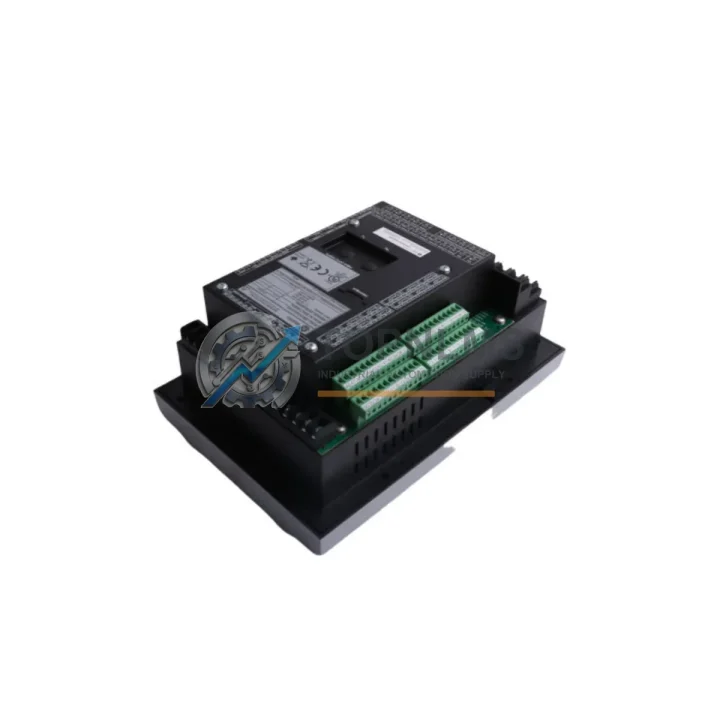
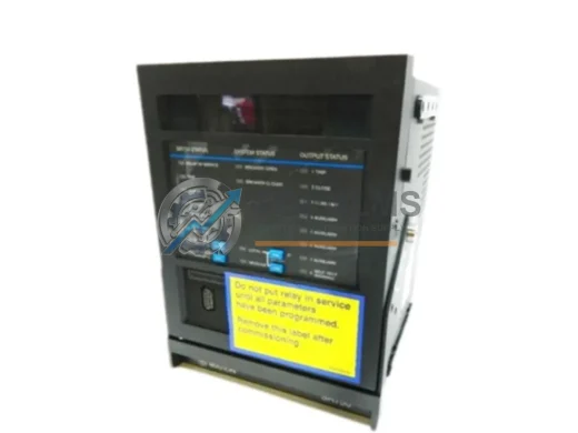
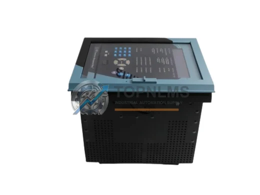
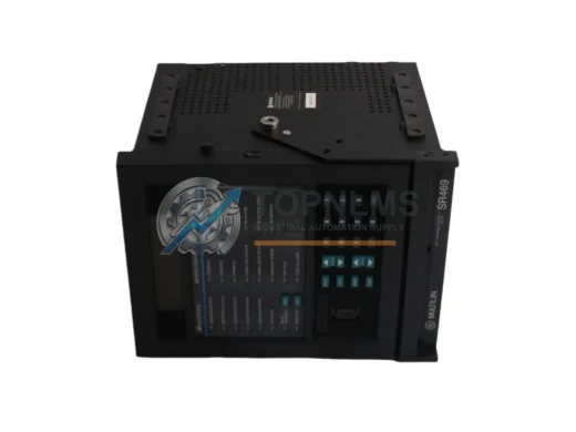
GE Multilin 369-HI-R-0-0-0-0-E Original Industrial Spare 369 Compatible: System Stability & Motor Protection Assurance
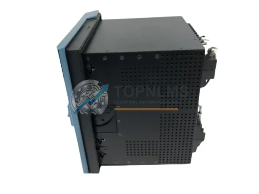
The GE Multilin 369-HI-R-0-0-0-0-E is a purpose-built motor management relay from GE’s trusted 369 Series, engineered for high-impedance ground fault detection and comprehensive motor protection in demanding industrial environments. Whether you are managing a continuous process plant, a water treatment facility, a mining operation, or a heavy manufacturing line, this relay is a cornerstone component in maintaining motor circuit integrity and preventing costly unplanned shutdowns.
Sourced directly from authorized supply channels, every unit stocked at TOPNLMS undergoes incoming inspection and functional verification before dispatch. We supply original, non-counterfeit components backed by a 12-month warranty, ensuring your maintenance team can install with confidence and your procurement team can plan with certainty.
Critical Technical Specs
| Parameter |
Specification |
| Model / SKU |
369-HI-R-0-0-0-0-E |
| Brand / Manufacturer |
GE Multilin (General Electric) |
| Series |
369 Motor Management Relay Series |
| Protection Function |
High-Impedance Ground Fault Detection, Motor Overload, Phase Unbalance, Undercurrent, Stall, Jam, Thermistor Input |
| Relay Output Type |
Electromechanical Relay (R suffix) |
| Communication |
RS-485 Modbus RTU (E suffix — EnerVista enabled) |
| Power Supply |
AC/DC Universal Input (refer to nameplate for exact range) |
| CT Input Range |
1–5 A secondary (compatible with standard motor protection CTs) |
| Mounting |
Panel / DIN rail, standard 369 Series cutout |
| Operating Temperature |
-20°C to +60°C |
| Enclosure / IP Rating |
IP40 front panel (flush mount) |
| Country of Origin |
United States |
| Weight |
3,560 g (approx.) |
| Compatibility |
Direct replacement for 369 Series variants; compatible with GE EnerVista 369 Setup Software |
| Warranty |
12 Months — TOPNLMS Quality Guarantee |
Preventive Maintenance Strategy
Motor protection relay failures rarely occur in isolation. When a 369-HI-R-0-0-0-0-E is flagged for replacement during a scheduled shutdown or emergency corrective maintenance event, experienced maintenance engineers know that the surrounding motor control circuit deserves equal scrutiny. A relay swap is the ideal moment to audit the full protection loop and address latent wear before it triggers the next trip.
Begin with the current transformer (CT) circuits feeding the 369 relay. Degraded CT insulation or loose secondary wiring is a common root cause of nuisance trips and misread ground fault currents — inspect and torque all CT terminal connections. Next, examine the motor control center (MCC) power supply module that energizes the relay’s auxiliary supply input; an unstable auxiliary voltage can cause relay resets and loss of event log data, undermining your post-fault analysis capability.
The RS-485 communication cable and termination resistors connecting the 369 relay to your SCADA or DCS host should be verified for continuity and correct impedance matching. Communication faults on the Modbus RTU network can silently prevent remote trip commands and alarm acknowledgements from reaching the control room. If your facility runs a GE Multilin 469 Motor Management Relay on larger motors in the same switchgear lineup, this is also a good time to cross-check firmware versions and parameter consistency across the protection fleet.
During the same outage window, inspect the auxiliary relay modules and output wiring downstream of the 369’s trip contacts. Relay output contacts accumulate arc erosion over thousands of operations; if the trip contact resistance has risen, the downstream motor contactor or circuit breaker shunt trip coil may not receive sufficient current to operate reliably. Verify contact resistance with a low-resistance ohmmeter and replace auxiliary relays showing excessive wear.
For motors equipped with embedded thermistor or RTD temperature sensors, confirm that the thermistor input wiring to the 369 relay is intact and that resistance readings fall within the expected cold/hot range for your motor class. A broken thermistor circuit can mask thermal overload conditions, allowing the motor to run into damaging temperature territory without triggering a protective trip.
Facilities managing aging motor control infrastructure should also review the condition of terminal blocks and DIN rail assemblies within the control cabinet. Loose or corroded terminals are a leading cause of intermittent relay malfunctions that are difficult to reproduce during bench testing. Replacing worn terminal blocks during a planned relay swap adds minimal labor cost but significantly improves long-term reliability.
Finally, if your plant uses a GE EnerVista 369 Setup Software interface for parameter configuration and event log retrieval, verify that the PC-to-relay RS-485 adapter and communication settings are current. Maintaining an up-to-date configuration backup of all 369 relay settings — including pickup levels, time delays, and curve selections — is a best practice that dramatically reduces recommissioning time after an emergency replacement.
Strategic Replacement Solutions
The 369-HI-R-0-0-0-0-E is a direct form-fit-function replacement for other 369 Series variants sharing the same relay output and communication configuration. When replacing an older 369 unit that has reached end-of-service life, the new relay can be configured using a saved EnerVista parameter file, reducing recommissioning time to under one hour in most cases — a critical advantage when production pressure is high and every minute of downtime carries a measurable cost.
For facilities still operating legacy GE Multilin motor protection relays from earlier generations, the 369 Series offers a significant upgrade path: improved ground fault sensitivity, expanded event logging, and native Modbus RTU communication eliminate the need for separate protocol converters or add-on communication modules. The high-impedance ground detection capability of the HI variant is particularly valuable in resistance-grounded systems where conventional ground fault relays lack the sensitivity to detect early-stage insulation breakdown before it escalates to a full phase-to-ground fault.
Stocking one or two 369-HI-R-0-0-0-0-E units as critical spares in your MRO inventory is a proven strategy for reducing mean time to repair (MTTR) on motor protection incidents. Given typical lead times for specialty protection relays from OEM channels, a local spare eliminates the risk of extended motor outages while awaiting procurement. TOPNLMS maintains ready stock with same-day dispatch capability for verified orders, supporting both emergency breakdown scenarios and planned maintenance schedules.
Support FAQ
Q1: Is the 369-HI-R-0-0-0-0-E covered by a warranty, and what does it include?
Yes. Every unit supplied by TOPNLMS carries a 12-month warranty covering manufacturing defects and functional failures under normal operating conditions. Each relay is inspected and tested prior to shipment. If a unit fails within the warranty period, we provide a replacement or full refund after fault verification.
Q2: How do I verify compatibility with my existing 369 Series installation?
The 369-HI-R-0-0-0-0-E is compatible with all standard 369 Series panel cutouts and wiring harnesses. Confirm that your existing installation uses relay (R) output contacts and RS-485 Modbus RTU (E) communication. If your current unit has a different suffix combination, contact us with your full model number and we will confirm cross-compatibility or recommend the correct variant.
Q3: What is the recommended spare inventory strategy for this relay?
For facilities with three or more motors protected by 369 Series relays, we recommend maintaining a minimum of one spare unit on-site. For critical process motors where unplanned downtime carries high production loss, a two-unit buffer is advisable. Relay spares have a shelf life of 10+ years when stored in a dry, temperature-controlled environment, making them a cost-effective insurance policy against supply chain disruptions.
Q4: What pre-shipment testing is performed on each unit?
Each 369-HI-R-0-0-0-0-E unit undergoes visual inspection for physical damage, connector integrity check, and power-on functional verification before packaging. Units are shipped in anti-static, shock-protected packaging with a test record. Expedited shipping options are available for emergency breakdown orders.