Product Overview
GE F31X134EPRBEG1 FR00/0 Original Industrial Spare Series 90-30 Compatible: Ensuring System Stability in Critical Automation Environments
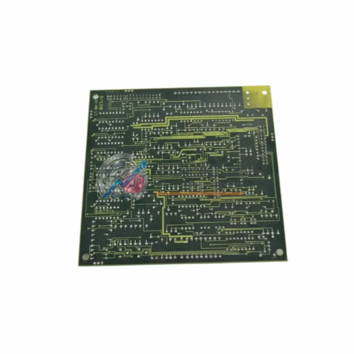
The GE F31X134EPRBEG1 FR00/0 Processor Interface Board is a core communication and processing component within the General Electric Series 90-30 PLC platform — one of the most widely deployed programmable logic controller families in global industrial automation. Designed to serve as the interface layer between the CPU module and the backplane bus, this board plays a decisive role in maintaining signal integrity, data throughput, and overall system reliability. For maintenance engineers managing aging control systems, securing an original spare of the F31X134EPRBEG1 FR00/0 is not merely a procurement decision — it is a risk management strategy.
In facilities where Series 90-30 PLCs govern continuous production lines, HVAC systems, water treatment processes, or discrete manufacturing cells, an unplanned failure of the processor interface board can cascade into full system shutdown. Unlike peripheral I/O faults that may allow partial operation, a failed interface board typically renders the entire CPU rack non-functional. Maintaining at least one verified spare on-site is the single most effective measure to reduce mean time to repair (MTTR) in these scenarios.
Critical Technical Specs
| Parameter |
Specification |
| Part Number |
F31X134EPRBEG1 |
| Firmware Revision |
FR00/0 |
| Manufacturer |
General Electric (GE Fanuc Automation) |
| Compatible Platform |
Series 90-30 PLC (GE 90-30 / IC693 Family) |
| Module Function |
Processor Interface Board — CPU-to-backplane communication |
| Backplane Compatibility |
IC693CHS391, IC693CHS392, IC693CHS393 and compatible 90-30 racks |
| Operating Voltage |
5 VDC (supplied via backplane) |
| Operating Temperature |
0°C to 60°C (32°F to 140°F) |
| Storage Temperature |
-40°C to 85°C |
| Humidity |
5% to 95% non-condensing |
| Mounting |
Direct insertion into Series 90-30 CPU module slot |
| Country of Origin |
United States |
| Product Condition |
Original / Genuine — tested before shipment |
| Warranty |
12 Months from date of purchase |
Preventive Maintenance Strategy: Protecting Your Series 90-30 Control System
When a maintenance team schedules a planned shutdown to inspect or replace the F31X134EPRBEG1 FR00/0, it is best practice to treat the event as a comprehensive control cabinet audit rather than a single-component swap. The Series 90-30 platform integrates tightly across its rack architecture, and degradation in one area often signals stress in adjacent components.
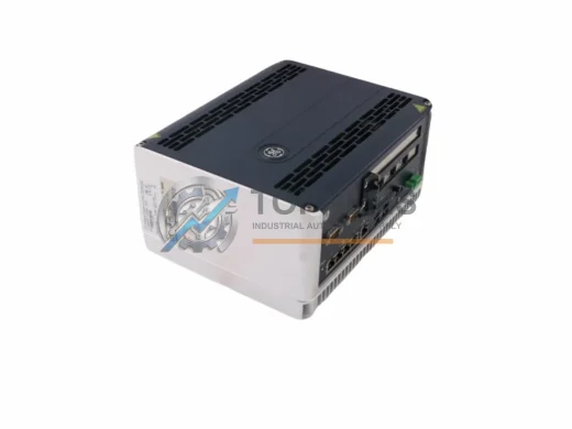
Begin with the power supply module — typically the IC693PWR321 or IC693PWR330 — as fluctuating DC bus voltage is a leading cause of premature interface board failure. A power supply delivering marginal 5 VDC output may not trigger an immediate fault but will accelerate wear on logic boards over months of operation. Replacing or bench-testing the power supply during the same maintenance window eliminates this hidden risk factor.
Next, inspect the CPU module itself, such as the IC693CPU374 or IC693CPU364, for signs of capacitor aging, corrosion on edge connectors, or firmware version mismatches. The processor interface board communicates directly with the CPU, and a CPU with degraded internal memory or clock circuitry will place abnormal load on the interface layer. If the CPU is approaching end-of-life, sourcing a replacement CPU module alongside the F31X134EPRBEG1 FR00/0 ensures the entire processing stack is renewed simultaneously.
Examine all I/O modules installed in the rack — discrete input modules such as the IC693MDL645 and analog output modules such as the IC693ALG390 should be checked for loose terminal connections, blown fuse indicators, and LED status anomalies. I/O module faults that go unresolved can generate excessive backplane traffic, indirectly stressing the processor interface board. Cleaning terminal blocks and verifying torque on field wiring connections takes less than thirty minutes per rack and significantly extends module service life.
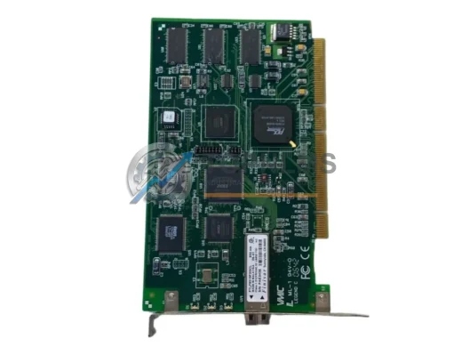
Communication modules deserve equal attention. If the control system uses Ethernet or serial communication — for example via the IC693CMM321 Communications Coprocessor or an IC693CMM302 Genius Bus Controller — verify that network cables are properly seated, shielding is intact, and communication parameters match the current SCADA or HMI configuration. A communication module operating with marginal signal quality will generate retries and timeouts that propagate through the backplane and increase processor load.
Do not overlook the backplane rack itself. Inspect the IC693CHS391 or equivalent chassis for bent guide rails, oxidized backplane connector pins, and any evidence of moisture ingress or insect contamination. A compromised backplane connector is one of the most misdiagnosed root causes of intermittent processor interface board faults. Cleaning connector pins with appropriate contact cleaner and verifying module seating torque resolves a significant percentage of apparent board failures without any component replacement.
Finally, review the condition of any signal isolators, terminal blocks, and fuse modules in the associated field wiring panels. Components such as DIN-rail mounted signal isolators and modular fuse terminal blocks protect the I/O layer from field-side transients. Replacing aging fuse elements and verifying isolator output calibration during the same maintenance event ensures that the newly installed F31X134EPRBEG1 FR00/0 operates in a clean electrical environment from day one.
Strategic Replacement Solutions: Extending Series 90-30 System Life
The GE Series 90-30 platform, while mature, remains operational in thousands of facilities worldwide due to its robust architecture, extensive installed base, and the continued availability of original spare parts. Replacing the F31X134EPRBEG1 FR00/0 with a genuine original component — rather than an aftermarket substitute — preserves full firmware compatibility, maintains CE and UL compliance documentation integrity, and eliminates the risk of undocumented behavioral differences that can arise with non-OEM boards.
For facilities managing a fleet of Series 90-30 racks, a strategic spare parts inventory should include at minimum one processor interface board per CPU type in service, one power supply module per rack configuration, and a rotating stock of the highest-utilization I/O modules. This tiered inventory approach, combined with a documented replacement procedure, allows maintenance personnel to restore system operation within minutes rather than hours — a critical advantage in continuous-process industries where every minute of downtime carries measurable production cost.
When replacing the F31X134EPRBEG1 FR00/0 in the field, power down the rack completely, discharge any residual bus voltage, and handle the board using ESD-safe procedures. Verify firmware revision compatibility with the installed CPU before insertion. After installation, perform a full I/O force test and communication loop check before returning the system to automatic mode. Document the replacement date, technician name, and board serial number in the equipment maintenance log to support future warranty claims and audit readiness.
All units shipped from TOPNLMS are individually tested for electrical continuity, logic function, and backplane interface integrity prior to dispatch. Each unit is packaged in anti-static shielding with protective foam inserts to prevent transit damage. Standard lead time is 1–3 business days for in-stock items, with expedited shipping available for urgent maintenance requirements.
Support FAQ
Q1: Is the F31X134EPRBEG1 FR00/0 compatible with all Series 90-30 CPU modules?
The F31X134EPRBEG1 FR00/0 is designed for use within the GE Series 90-30 PLC family. Compatibility depends on the specific CPU module and firmware revision in your rack. We recommend verifying the CPU part number (e.g., IC693CPU374, IC693CPU364) and cross-referencing with GE Fanuc compatibility documentation before installation. Our technical team can assist with compatibility verification prior to purchase.
Q2: What testing is performed before shipment, and what does the 12-month warranty cover?
Every F31X134EPRBEG1 FR00/0 unit undergoes electrical continuity testing, logic function verification, and backplane interface checks before dispatch. The 12-month warranty covers manufacturing defects and functional failures under normal operating conditions. It does not cover damage resulting from incorrect installation, overvoltage events, or physical mishandling. Warranty claims are processed within 5 business days of receipt of the returned unit.
Q3: How should I manage spare parts inventory for an aging Series 90-30 system?
For systems with 5 or more years of remaining planned service life, we recommend maintaining a minimum of one processor interface board, one power supply module, and two of each high-utilization I/O module type as on-site spares. For critical continuous-process applications, a complete spare CPU rack assembly provides the fastest possible recovery path. Periodic review of spare parts inventory against actual system configuration prevents gaps caused by undocumented field modifications.
Q4: Can I return the unit if it does not resolve my system fault?
Yes. If the F31X134EPRBEG1 FR00/0 does not resolve the diagnosed fault and is returned in its original, uninstalled condition within 30 days of receipt, we will process a full refund or exchange. We strongly recommend performing a systematic fault isolation procedure — including power supply verification, backplane inspection, and CPU diagnostics — before concluding that the processor interface board is the root cause of the fault. Our technical support team is available to assist with remote fault diagnosis at no charge.