Product Overview
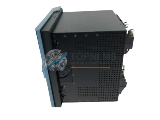
GE 369-HI-R-M-0-0-0-E Original Industrial Spare 369 Compatible: System Stability & Motor Protection Value
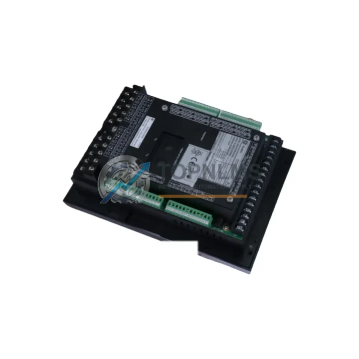
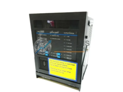
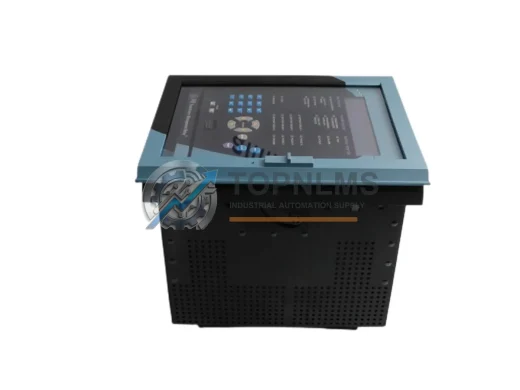
The GE 369-HI-R-M-0-0-0-E is a full-featured motor management relay from GE’s renowned 369 Series, engineered for continuous-duty industrial motor protection in demanding plant environments. Whether you are managing a petrochemical facility, a water treatment plant, a mining operation, or a heavy manufacturing line, this relay serves as the cornerstone of your motor protection strategy. Its comprehensive protection functions — including thermal overload, phase unbalance, undercurrent, ground fault, and jam detection — make it an indispensable component for maintaining system uptime and preventing catastrophic motor failures.
For maintenance engineers and reliability teams, having a verified original 369-HI-R-M-0-0-0-E unit in stock is not a luxury — it is a risk management decision. Unplanned motor failures in critical process lines can result in hours or days of downtime, with cascading effects on production schedules and safety compliance. Stocking this relay as a certified spare eliminates the lead-time risk associated with emergency procurement and ensures that your team can execute a like-for-like replacement without reconfiguration delays.
Each unit supplied by TOPNLMS is sourced from authorized channels, inspected prior to dispatch, and covered by a 12-month warranty. We ship globally with full documentation support, including test records and original packaging where available.
Critical Technical Specs Table
| Parameter |
Specification |
| Model / SKU |
369-HI-R-M-0-0-0-E |
| Series |
GE 369 Motor Management Series |
| Product Type |
Motor Management / Protection Relay |
| Manufacturer |
GE (General Electric / GE Grid Solutions) |
| Input Voltage (Control) |
100–240 VAC / 125–250 VDC (High Voltage Input variant) |
| CT Input Range |
0.5–5000 A (via external CTs) |
| Protection Functions |
Thermal overload, phase unbalance, ground fault, undercurrent, jam, stall, starts-per-hour, RTD monitoring |
| RTD Inputs |
Up to 12 RTD inputs (motor winding & bearing temperature) |
| Communication |
RS-485 Modbus RTU (standard); optional DeviceNet / Profibus |
| Relay Outputs |
Multiple trip and alarm output relays |
| Display |
Front-panel LCD with LED indicators |
| Mounting |
Panel / rack mount, standard 19″ cutout compatible |
| Operating Temperature |
-20°C to +60°C |
| Ingress Protection |
IP54 front panel (panel-mounted) |
| Weight |
Approx. 3.62 kg |
| Origin |
United States |
| Compatibility |
Direct replacement for GE 369 Series variants; compatible with existing 369 wiring harnesses and CT configurations |
| Warranty |
12 Months — TOPNLMS Quality Guarantee |
| Pre-shipment Testing |
Functional inspection and power-on verification performed before dispatch |
Preventive Maintenance Strategy
A motor protection relay does not operate in isolation. The 369-HI-R-M-0-0-0-E sits at the center of a broader motor control and protection ecosystem, and a disciplined preventive maintenance program must account for all interdependent components to be truly effective.
During scheduled shutdowns or annual motor inspections, maintenance teams should treat the 369 relay replacement as an opportunity to audit the entire motor feeder circuit. The current transformers (CTs) supplying the relay’s current inputs are a common source of measurement drift over time — worn or saturated CTs can cause nuisance trips or, worse, missed fault detection. Replacing or recalibrating CTs in tandem with a relay swap ensures measurement integrity from day one.
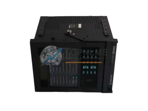
The GE 469 Motor Management Relay is the natural upgrade path for larger motors or applications requiring more advanced protection algorithms. If your facility operates a mixed fleet of motors, maintaining spares for both the 369 and 469 platforms reduces the risk of a single-point procurement failure during a multi-motor outage event.
Control power to the 369-HI-R-M-0-0-0-E is typically supplied through a dedicated 24 VDC or 120 VAC power supply module within the MCC (Motor Control Center) or switchgear panel. These power supplies are subject to capacitor aging and voltage ripple degradation — a failed control power supply will render the relay inoperative regardless of its own condition. Inspecting and stocking a compatible DIN-rail power supply (such as a Phoenix Contact QUINT or equivalent) as part of your MCC spare parts kit is strongly recommended.
The relay’s RS-485 Modbus communication link connects it to your SCADA or DCS system. RS-485 signal isolators and communication repeaters in long cable runs are often overlooked during maintenance cycles. A degraded communication link can cause intermittent data loss in your historian, masking early warning trends. Checking the integrity of the Belden 9841 or equivalent shielded twisted-pair communication cable during each inspection interval is a low-cost, high-value task.
Within the same MCC bucket, the contactor and overload relay (if a separate thermal overload is used in parallel with the 369) should be inspected for contact wear and coil resistance. GE’s CL-series contactors are commonly paired with 369 relays in legacy installations. Worn contactor tips increase inrush current asymmetry, which can trigger nuisance phase-unbalance trips on a correctly calibrated 369 relay.
For facilities using the 369’s RTD monitoring capability, the PT100 RTDs embedded in motor windings and bearings represent another critical spare category. RTD lead wire degradation, connector corrosion, and sensor drift are common failure modes in high-vibration or high-humidity environments. Stocking a set of replacement RTDs and RTD extension cables ensures that temperature monitoring remains accurate throughout the motor’s service life.
Finally, the terminal blocks and DIN-rail mounting hardware within the relay panel deserve attention. Loose terminal connections are a leading cause of intermittent relay malfunctions and can be misdiagnosed as relay failures. A torque-check of all wiring terminations — particularly the CT secondary circuits — should be a mandatory step in every 369 relay maintenance procedure. Stocking Phoenix Contact or Weidmuller terminal blocks compatible with your existing rail configuration ensures rapid panel restoration after any wiring fault.
Strategic Replacement Solutions
The GE 369-HI-R-M-0-0-0-E is a direct replacement for earlier 369 Series variants, including units with different suffix configurations that share the same physical form factor and wiring interface. This backward compatibility is a significant operational advantage: your existing CT wiring, control power connections, and communication cabling can be retained without modification, reducing replacement time from hours to minutes in a well-prepared maintenance scenario.
For facilities managing aging motor control infrastructure — particularly MCC lineups installed in the 1990s and 2000s — the 369 relay represents a cost-effective alternative to full MCC replacement. Rather than investing in a complete switchgear upgrade, a targeted relay replacement program using original 369-HI-R-M-0-0-0-E units extends the operational life of existing infrastructure by 5–10 years, deferring capital expenditure while maintaining protection performance equivalent to current standards.
When planning a replacement, TOPNLMS recommends pre-configuring the replacement relay using GE’s 369 PC software before the maintenance window begins. Settings files from the outgoing relay can be exported, reviewed, and loaded into the new unit in advance, so that the physical swap and commissioning can be completed within a single planned outage window — typically under two hours for an experienced technician.
For sites transitioning toward IEC 61850 or Ethernet-based protection architectures, the 369’s Modbus RTU interface can be bridged to modern SCADA systems using protocol converters, preserving the investment in existing relay infrastructure while enabling integration with contemporary data acquisition platforms.
Support FAQ
Q1: Is the 369-HI-R-M-0-0-0-E a direct drop-in replacement for other 369 Series variants?
A: Yes. The 369-HI-R-M-0-0-0-E shares the same physical housing, terminal layout, and wiring interface as other 369 Series relays. In most installations, it can replace earlier or alternate-suffix 369 units without panel modifications. We recommend verifying your existing settings file and CT ratio configuration before commissioning the replacement unit.
Q2: What does the 12-month warranty cover, and what pre-shipment checks are performed?
A: Every 369-HI-R-M-0-0-0-E unit shipped by TOPNLMS undergoes a functional power-on inspection and basic operational verification before dispatch. The 12-month warranty covers manufacturing defects and functional failures under normal operating conditions. Units showing physical damage caused by incorrect installation, overvoltage events, or environmental exposure beyond rated limits are excluded. Warranty claims are processed promptly with replacement or repair options.
Q3: How should I manage 369 relay inventory for a multi-motor facility?
A: For facilities with 10 or more motors protected by 369 Series relays, we recommend maintaining a minimum of one spare relay per 10 protected motors, with a floor of two units regardless of fleet size. For critical process motors (pumps, compressors, fans serving safety systems), a dedicated one-for-one spare is best practice. Relays in storage should be kept in their original packaging in a dry, temperature-controlled environment and powered up annually to verify functionality.
Q4: Can compatibility be verified before purchase for my specific installation?
A: Yes. Please provide your existing relay’s full model number, nameplate data, and CT ratio information to our technical team at [email protected]. We will confirm compatibility with your installation before order confirmation. For complex or multi-relay installations, we can also assist with settings file review and pre-configuration services.