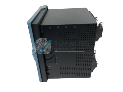
Product Overview
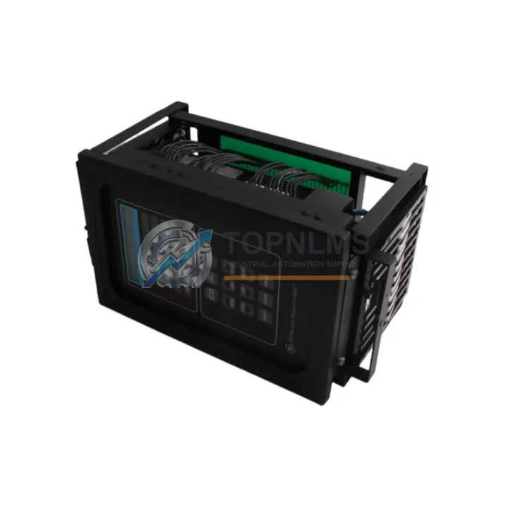
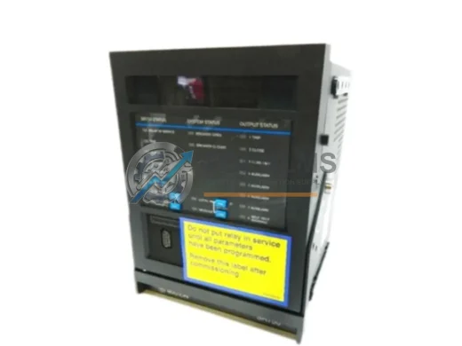
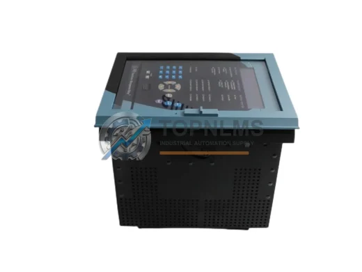
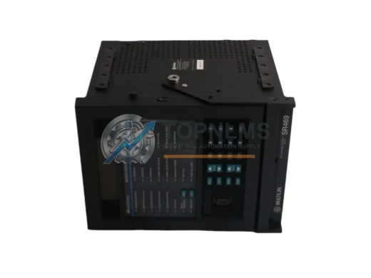
GE 269P-D/O-278-100P-HI Replacement for Multilin 269 Plus: Seamless Transition & Legacy System Compatibility
When your GE Multilin 269 Plus motor management relay reaches end-of-life or becomes difficult to source, unplanned downtime is the greatest operational risk. The GE 269P-D/O-278-100P-HI is a direct replacement and upgrade solution engineered for facilities running legacy motor protection systems across pump stations, compressor drives, conveyor lines, and critical process motors. This unit preserves your existing wiring infrastructure, control cabinet layout, and SCADA communication architecture — enabling a smooth migration without costly re-engineering.
The 269P-D/O-278-100P-HI is part of GE Grid Solutions’ Multilin 269 Plus platform, a widely deployed motor management relay series trusted in oil & gas, water treatment, mining, and heavy manufacturing. Its 100P high-impedance differential input configuration, combined with the D/O (drawout) form factor and 278 VA burden rating, makes it a precise match for installations originally designed around the Multilin 269 series architecture. Whether you are replacing a failed unit, building a critical spare inventory, or executing a planned retrofit, this relay delivers the protection functions — thermal overload, phase unbalance, ground fault, undercurrent, and jam detection — that your motor control center (MCC) depends on.
Compatibility Comparison Table
| Parameter |
Original / Legacy Unit |
GE 269P-D/O-278-100P-HI (Replacement) |
| Model / SKU |
GE Multilin 269 Plus (various suffixes) |
269P-D/O-278-100P-HI |
| Form Factor |
Drawout (D/O) panel-mount |
Drawout (D/O) — direct mechanical fit |
| CT Input Burden |
278 VA |
278 VA — identical burden rating |
| Current Input Range |
100P (high-impedance, 100:1 ratio) |
100P — same CT ratio, no rewiring required |
| Communication Protocol |
RS-485 Modbus RTU / DNP3 |
RS-485 Modbus RTU / DNP3 — protocol compatible |
| Protection Functions |
Thermal overload, phase unbalance, ground fault, jam, undercurrent |
Full parity — all protection elements retained |
| Mounting / Cutout |
Standard Multilin 269 panel cutout |
Same cutout dimensions — no panel modification |
| Wiring Terminals |
Existing terminal block layout |
Compatible terminal assignment — reuse existing wiring |
| Programming / Configuration |
EnerVista 269 Plus Setup Software |
Compatible with EnerVista 269 Plus — settings transferable |
| Warranty |
OEM warranty (expired on legacy units) |
12-Month Warranty from TOPNLMS |
Seamless Upgrade Solutions
A successful migration from a legacy Multilin 269 Plus installation rarely involves only the relay itself. In practice, field engineers replacing the 269P-D/O-278-100P-HI frequently address adjacent components to ensure system-wide reliability. The RS-485 communication wiring connecting the relay to a DCS or SCADA host often requires a GE Multilin RS-485 to Ethernet gateway or a compatible Modbus RTU communication module if the upstream system has been upgraded to Ethernet-based protocols. In MCC lineups where multiple 269 Plus relays are daisy-chained, replacing one unit is a natural trigger to audit the GE Multilin 369 Motor Management Relay units in adjacent feeders, particularly if those units share the same firmware generation and are approaching the same end-of-service window.
On the power supply side, the 269P-D/O-278-100P-HI operates from a standard control voltage supply; however, aging MCCs may have deteriorating 24 VDC or 120 VAC auxiliary power modules that should be replaced concurrently to avoid nuisance trips after commissioning the new relay. For facilities using GE Multilin 239 Motor Protection Relay units on smaller motors in the same switchgear lineup, a coordinated replacement plan covering both the 239 and 269 Plus platforms reduces future maintenance windows.
Where the motor being protected is driven by a variable frequency drive (VFD), the retrofit may also involve verifying compatibility between the 269P-D/O-278-100P-HI and the GE AF-600 FP or PowerFlex-compatible drive interface, particularly for the analog speed reference and digital run/fault signals wired into the relay’s I/O terminals. In installations where a GE Multilin 750/760 Feeder Protection Relay provides upstream overcurrent protection, the coordination curves should be re-verified after the 269 Plus replacement to maintain selectivity. Finally, if the MCC uses a GE Multilin EPM power meter on the same RS-485 bus, the Modbus device address assignment must be confirmed to avoid address conflicts after the new relay is commissioned.
Retrofit Guidance FAQ
Q: Can I reuse my existing CT wiring when installing the 269P-D/O-278-100P-HI?
A: Yes. The 100P input designation specifies a 100:1 CT ratio with 278 VA burden, which matches the original installation. Existing phase CT and ground CT wiring can be reconnected to the same terminal positions without modification, provided the CT secondary leads are properly shorted during the swap to prevent open-circuit voltage hazards.
Q: Will my EnerVista 269 Plus configuration file work on the replacement unit?
A: In most cases, yes. Configuration files created with GE’s EnerVista 269 Plus Setup Software are portable across units of the same model designation. After uploading the saved .cfg file, verify all setpoints on the relay’s front panel display and perform a functional test of each protection element before returning the motor to service.
Q: Does the drawout (D/O) form factor require any panel modification?
A: No. The D/O chassis is designed for tool-free withdrawal and insertion into the standard Multilin 269 Plus drawout cradle. The panel cutout, mounting rails, and rear terminal block remain unchanged. This is one of the primary advantages of the drawout form factor for maintenance and emergency replacement scenarios.
Q: How do I re-establish Modbus RTU communication after replacement?
A: Set the Modbus device address on the new relay to match the address previously assigned to the failed unit. Verify baud rate (typically 9600 or 19200 bps), parity, and stop bit settings match the host SCADA or DCS configuration. The RS-485 bus termination resistor at the end of the daisy chain should remain in place; do not add additional termination at the new relay unless it is the last device on the bus.
Q: What physical space is required in the control cabinet?
A: The 269P-D/O-278-100P-HI occupies the same panel depth and width as the original Multilin 269 Plus drawout unit. No additional DIN rail space or cable management modifications are required. Confirm that the existing drawout cradle is mechanically sound and that the rear terminal block contacts are clean and undamaged before inserting the replacement unit.
Q: Can this relay be used as a cold standby spare?
A: Yes. The unit can be pre-configured with your site’s setpoints using EnerVista software and stored as a tested cold standby spare. TOPNLMS recommends pre-commissioning and function-testing all spare relays upon receipt to confirm operability before they are needed in an emergency.
Warranty Assurance
Every GE 269P-D/O-278-100P-HI unit shipped by TOPNLMS is covered by a 12-month warranty from the date of delivery. Prior to shipment, each unit undergoes a multi-point outgoing inspection that includes visual examination, power-on functional verification, and communication port testing. Units that do not pass inspection are not shipped.
In the event of a warranty claim, TOPNLMS provides a replacement unit or full refund based on the confirmed fault condition. Our technical support team responds to warranty inquiries within one business day. We maintain stock of the 269P-D/O-278-100P-HI and related Multilin 269 Plus components to support rapid replacement dispatch, minimizing the time your motor protection system operates without a qualified relay in service.
For procurement teams managing critical spare inventories, TOPNLMS can provide batch testing documentation, individual serial number records, and packing inspection photos upon request. All units are shipped in anti-static protective packaging with foam cushioning suitable for international air and sea freight.
Lead time for in-stock units is typically 3–7 business days for international destinations. Express shipping options are available for emergency replacement scenarios. Contact our team to confirm current stock availability and lead time before placing your order.