FUJI Electric
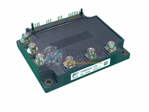
Fuji Electric 7MBI50N-120 Replacement for N-Series
7MBI50N-120Drop-in replacement for Fuji Electric 7MBI50N-120 N-Series IGBT module, 50A/1200V. Compatibility verified, 12-month warranty, fast global shipping from Xiamen.
Request availability, condition, lead time and export shipping details for 2MBI75N-120.
Send this exact part number, quantity and destination country. TOPNLMS will confirm availability, condition and export lead time before quotation.
The Fuji Electric 2MBI75N-120 is a 75A / 1200V dual IGBT power module engineered for high-reliability industrial drive and inverter applications. As legacy inverter platforms age and OEM support windows close, plant engineers and procurement teams increasingly seek a verified, drop-in replacement that preserves existing wiring harnesses, gate-drive circuits, and control-board interfaces without requiring a full drive redesign. This page is dedicated to helping you execute that migration with confidence.
Whether you are retiring a Fuji Electric FRENIC or FRNC series variable-frequency drive, replacing a failed module in a Yaskawa G7 or F7 drive platform, or modernizing a Mitsubishi FR-A700 inverter cabinet, the 2MBI75N-120 fits the standard 62 mm dual-inline package (DIP) footprint shared across the 2MBI Series. The collector–emitter voltage rating of 1200 V and continuous collector current of 75 A align directly with the original design envelope, meaning your existing DC bus capacitor bank, snubber network, and gate-resistor values remain valid without recalculation.
Procurement teams sourcing this module as a spare or emergency replacement will find that TOPNLMS maintains ready stock, performs outgoing electrical verification on every unit, and ships from Xiamen within 1–3 business days via DHL Express or FedEx International Priority to minimize production downtime.
| Parameter | 2MBI75N-120 (This Unit) | Typical Legacy Equivalent | Replacement Notes |
|---|---|---|---|
| Part Number | 2MBI75N-120 | 2MBI75N-120-50 / 2MBI75L-120 | Direct pin-compatible; verify suffix for gate-drive voltage |
| VCES (Collector–Emitter) | 1200 V | 1200 V | No bus-voltage derating required |
| IC (Continuous) | 75 A | 75 A | Thermal interface pad reuse acceptable |
| Package / Footprint | 62 mm DIP (2-in-1) | 62 mm DIP (2-in-1) | Existing heatsink and mounting hardware retained |
| Gate Drive Voltage | ±15 V recommended | ±15 V | No gate-driver board modification needed |
| Isolation Voltage | 2500 V AC (1 min) | 2500 V AC | Meets IEC 60747-9 creepage requirements |
| Communication / Control Interface | Passive power device — no comms bus | N/A | Upper-level drive controller (e.g., Fuji FRENIC CPU board) unchanged |
| Mounting Torque | 3 N·m (M5 screw) | 3 N·m | Apply fresh thermal compound; torque to spec |
| Origin | Japan | Japan | OEM-grade quality standard maintained |
| Warranty | 12 Months | Varies (OEM EOL) | TOPNLMS 12-month replacement warranty included |
A successful 2MBI75N-120 field replacement rarely involves the IGBT module alone. In practice, the migration touches several adjacent components within the same drive cabinet or inverter rack. Below is a description of the typical upgrade workflow and the related components that commonly require attention during the same service window.
The gate-drive board — often a Fuji Electric EG2401 or equivalent isolated gate-driver card — should be inspected for carbon tracking or degraded bootstrap capacitors before the new IGBT is powered up. If the gate-driver output impedance has drifted, the switching losses of the new 2MBI75N-120 will be higher than specified, shortening its service life. In many FRENIC-series drives, the gate-driver card is a plug-in sub-assembly that can be replaced independently without disturbing the main control PCB.
The DC bus capacitor bank — typically a bank of 450 V or 800 V electrolytic capacitors mounted on the same heatsink assembly — should be ESR-tested during the same outage. Capacitors that have been in service for more than five years in a 40 °C ambient environment are statistically near end-of-life and represent the next most likely failure point after the IGBT module itself.
For drives that use a Fuji Electric OPC-G1-RJ45 or OPC-G1-PROFIBUS communication option card, the fieldbus connection to the upstream PLC or DCS remains entirely unaffected by the IGBT swap. The communication option card plugs into the drive’s control board and is electrically isolated from the power stage. Engineers migrating from a Siemens S7-300 or S7-400 PLC platform via PROFIBUS DP, or from an Allen-Bradley ControlLogix system via EtherNet/IP, will find that the drive’s parameter set and network node address are preserved in non-volatile memory and do not need to be re-entered after the module replacement.
Where the drive is integrated into a Mitsubishi MELSEC Q-series or iQ-R series control architecture using CC-Link or CC-Link IE Field, the same principle applies: the IGBT replacement is transparent to the network layer. The drive’s station number, baud rate, and I/O mapping remain intact. Only the physical power stage is disturbed.
In cabinet installations where the drive shares a 24 V DC control power supply — such as a Phoenix Contact QUINT or a Siemens SITOP PSU — with other field devices including signal isolators, terminal relay modules, and I/O marshalling strips, it is good practice to verify that the inrush current during drive re-energization does not trip the electronic circuit breaker protecting the 24 V rail. A signal isolator (e.g., a Weidmüller ACT20P or equivalent) on any analog speed-reference input to the drive should also be checked for correct zero/span calibration after the power cycle.
Finally, if the drive is mounted in a Rittal TS 8 or AE series enclosure with a top-mounted heat exchanger, confirm that the heatsink fin orientation of the replacement 2MBI75N-120 matches the airflow direction. Reversed airflow across the module fins can increase junction temperature by 8–12 °C under full load, which is sufficient to reduce IGBT lifetime by a factor of two at rated current.
Q: Do I need to re-program the drive after replacing the 2MBI75N-120?
No. The 2MBI75N-120 is a passive power semiconductor. Drive parameters, PID tuning values, acceleration/deceleration ramps, and communication settings stored in the drive’s EEPROM are unaffected by the module swap. After replacement, perform a no-load test run and verify output current symmetry across all three phases before reconnecting the motor.
Q: Is the wiring harness compatible with the replacement module?
Yes. The 2MBI75N-120 uses the standard 62 mm DIP terminal layout. Gate (G), emitter (E), and collector (C) terminals are in the same positions as the original. Re-use existing gate-drive wiring without modification. Torque all power terminals to 3 N·m and apply fresh thermal compound to the heatsink interface.
Q: What communication protocols are supported in the wider system?
The IGBT module itself has no communication interface — it is a power device. The drive’s communication capability (PROFIBUS DP, EtherNet/IP, Modbus RTU, CC-Link, DeviceNet) is determined by the option card installed in the drive’s control board, which is not affected by the power module replacement.
Q: Will the replacement module fit in the existing control cabinet without mechanical modification?
Yes, provided the original module was a 62 mm DIP 2-in-1 package. The 2MBI75N-120 shares the same mounting hole pattern, terminal positions, and heatsink contact area. No drilling, bracket fabrication, or busbar modification is required.
Q: How do I verify the replacement module before installation?
Use a digital multimeter in diode-test mode to verify forward voltage drop across each IGBT’s body diode (typically 0.4–0.7 V) and confirm no short-circuit between collector and emitter. TOPNLMS performs this verification on every unit prior to shipment and includes a test record with each order.
Q: What if the original failure was caused by a gate-driver fault rather than the IGBT itself?
Installing a new IGBT module without diagnosing and correcting the root cause of the original failure is the most common reason for repeat failures. Always scope the gate-drive signal (target: clean 15 V / −8 V square wave with rise time < 200 ns) before powering up the replacement module. If the gate-driver board shows signs of damage, replace it concurrently.
Every Fuji Electric 2MBI75N-120 unit shipped by TOPNLMS is covered by a 12-month replacement warranty from the date of delivery. Our warranty process is straightforward: if the module fails under normal operating conditions within the warranty period, we ship a replacement unit at no charge within 3 business days of receiving your failure report and photographic evidence. No lengthy RMA bureaucracy.
Pre-shipment testing: Each unit undergoes electrical verification including collector–emitter leakage current (ICES), gate threshold voltage (VGE(th)), and diode forward voltage (VF) measurement before packaging. A test record is included in the shipment.
Packaging: Modules are shipped in anti-static foam-lined boxes with corner protection. For international shipments, an outer carton with desiccant is used to prevent moisture ingress during transit.
Lead time: In-stock units ship within 1–3 business days from Xiamen, China. DHL Express and FedEx International Priority are the standard carriers. Estimated transit time to most destinations in Asia, Europe, and North America is 3–7 business days.
After-sales support: Our technical team is available via email at [email protected] or by phone at +86 18359293191 to assist with installation questions, compatibility verification, and failure analysis.
Procurement assurance: TOPNLMS issues a commercial invoice, packing list, and certificate of origin with every shipment. For customers requiring third-party inspection or specific export documentation, please contact us before placing your order.
Drop-in replacement for Fuji Electric 7MBI50N-120 N-Series IGBT module, 50A/1200V. Compatibility verified, 12-month warranty, fast global shipping from Xiamen.
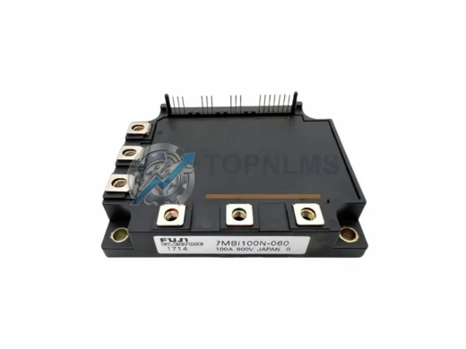
FUJI Electric 7MBI100N-060 original 6-in-1 IGBT power module, 100A/600V, 7MBI series. Fast shipping, 12-month warranty. Industrial replacement for inverter drives.
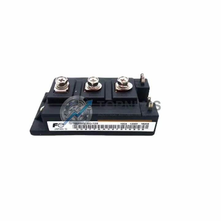
FUJI Electric 6RI50E-060 three-phase rectifier bridge module, 50A/600V. Rugged, reliable industrial power component. 12-month warranty. Fast global shipping.

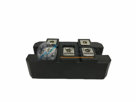
Original Fuji Electric 6R6D50A-050BHX FRENIC Series AC drive power module. Industrial spare for fast replacement, system compatibility & 12-month warranty.
Click Quote This Model and the Part Number field will auto-fill with 2MBI75N-120.