Product Overview
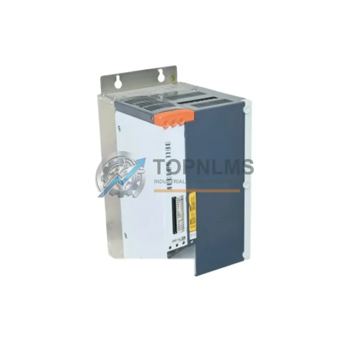
B&R 8V1180.001-2 Replacement for ACOPOS Multi — Smooth Transition, Zero Compromise
When a B&R ACOPOS Multi servo drive fails or reaches end-of-life, every minute of unplanned downtime translates directly into production loss. The B&R 8V1180.001-2 is an 18 kW AC servo drive module from the ACOPOS Multi platform — a high-performance, modular drive system widely deployed in packaging machinery, printing lines, semiconductor handling, and precision motion control applications. At TOPNLMS, we maintain verified stock of the 8V1180.001-2 to support both emergency replacement and planned upgrade scenarios, ensuring your transition from an aging or failed unit is as seamless as possible.
Whether you are replacing a failed drive in an existing ACOPOS Multi rack or migrating from an older ACOPOS 1000/1010 single-axis drive architecture to the more compact ACOPOS Multi multi-axis topology, the 8V1180.001-2 delivers the same B&R motion kernel compatibility, POWERLINK communication backbone, and ACOPOSmulti software integration your engineering team already knows. This means your existing motion programs, axis parameters, and PLC logic developed in Automation Studio require minimal rework — a critical advantage when production schedules cannot accommodate extended commissioning windows.
Compatibility Comparison Table
| Parameter |
B&R 8V1180.001-2 (This Unit) |
Typical Legacy Reference |
| Platform |
ACOPOS Multi |
ACOPOS 1000 / 1010 Single-Axis |
| Continuous Output Power |
18 kW |
Varies by legacy model |
| Supply Voltage |
3 × 400–480 V AC, 50/60 Hz |
3 × 400–480 V AC |
| Communication Protocol |
POWERLINK (integrated) |
POWERLINK / CAN (model-dependent) |
| Axis Configuration |
Multi-axis module (shared DC bus) |
Single-axis (independent DC bus) |
| Mounting |
ACOPOS Multi rack / bookshelf |
DIN rail or panel mount |
| Programming Environment |
B&R Automation Studio 4.x+ |
Automation Studio 3.x / 4.x |
| Motor Feedback Interface |
EnDat 2.2, resolver, incremental |
EnDat 2.1/2.2, resolver |
| Safe Motion (STO/SLS) |
Integrated (IEC 62061 / PLe) |
External safety relay required (older) |
| Replacement Recommendation |
Direct slot replacement in ACOPOS Multi rack |
Requires rack adapter or rewiring for cross-platform |
| Warranty |
12-Month Warranty — All units tested before shipment |
Seamless Upgrade Solutions
A successful ACOPOS Multi drive replacement rarely involves the drive module alone. In practice, the 8V1180.001-2 operates within a tightly integrated motion architecture, and a thorough upgrade plan should account for the surrounding components that share the same DC bus, rack, and communication network.
The 8V1180.001-2 slots into an ACOPOS Multi rack alongside a line filter module (such as the 8B0F series) and a mains module (8BVP or 8B0M series) that supplies the shared DC bus. If the mains module or its associated DC bus capacitor module shows signs of aging — swollen capacitors, elevated ripple current, or thermal discoloration — it is strongly advisable to replace these concurrently rather than stress a new drive with a degraded power supply stage. Similarly, the 8V1180.001-2 connects to servo motors via shielded motor cables; inspecting and, where necessary, replacing the motor power cable and feedback cable (typically EnDat 2.2 or resolver type) eliminates a common source of post-replacement faults.
On the communication side, the ACOPOS Multi platform relies on B&R POWERLINK running over standard Ethernet cabling. If your control cabinet also houses a B&R X20 PLC system — for example an X20CP1586 or X20CP3586 controller — verify that the POWERLINK cycle time and node address configuration in Automation Studio matches the replacement drive’s firmware version. In multi-axis installations, the 8V1022.001-2 or 8V1040.001-2 lower-power modules on adjacent axes should also be inspected for firmware consistency, as mixed firmware versions on the same POWERLINK segment can cause synchronization errors during commissioning.
For cabinet-level integration, confirm that the 24 V DC control power supply feeding the ACOPOS Multi rack’s logic circuits — often a B&R or Phoenix Contact unit — delivers stable voltage within the ±5% tolerance specified for the drive’s control board. A marginal power supply that was adequate for an older drive may not sustain the inrush demands of a new module during initialization. Additionally, if your installation uses a B&R Panel PC or Power Panel HMI for operator-level diagnostics and parameter visualization, ensure the Automation Studio project’s HMI mappings are updated to reflect any axis renumbering that may occur when the replacement drive is assigned a new POWERLINK node ID.
Finally, for facilities managing a broader B&R motion platform, it is worth auditing the 8AC114.60-1 or 8AC122.60-1 ACOPOSmulti inverter modules on adjacent axes and the X20DO series digital output modules used for enable signals and brake control — components that interact directly with the drive’s safety and I/O interface and are frequently overlooked during single-axis replacement projects.
Retrofit Guidance FAQ
Q1: Can the 8V1180.001-2 replace an older ACOPOS 1010 single-axis drive without rewiring the motor?
A: A direct motor cable swap is possible if the motor uses a standard EnDat 2.2 or resolver feedback interface and the cable pinout matches the ACOPOS Multi connector standard. However, the ACOPOS Multi uses a different rack-mount power connector than the standalone ACOPOS 1010, so the DC bus and mains wiring must be adapted to the multi-axis rack architecture. We recommend reviewing the B&R ACOPOS Multi User’s Manual (document 8V1xxx) and consulting your system integrator before proceeding.
Q2: Do I need to update my Automation Studio project after installing the replacement drive?
A: If the replacement unit carries the same hardware revision and firmware version as the original, the existing Automation Studio project can typically be used without modification. If the firmware version differs, Automation Studio will prompt a firmware update during the next project transfer. Always back up the existing project and perform a controlled download in a maintenance window to avoid unexpected axis behavior.
Q3: How do I verify POWERLINK communication after installation?
A: After physical installation, power up the rack and use Automation Studio’s online diagnostic view to confirm the replacement drive appears on the POWERLINK network with the correct node address and operational state (OPERATIONAL, not PRE-OPERATIONAL). Check the drive’s status LEDs — a steady green POWERLINK LED indicates successful network integration. If the drive remains in PRE-OPERATIONAL state, verify the node address DIP switch setting matches the original configuration.
Q4: What physical space and cooling requirements should I check before installation?
A: The 8V1180.001-2 is a bookshelf-format module designed for the ACOPOS Multi rack. Confirm the rack has a free slot of the correct width for an 18 kW module (wider than lower-power variants). Ensure the cabinet’s forced-air cooling system — typically a top-mounted fan unit — is operational and that the air inlet filters are clean. The drive’s thermal derating curve begins above 40 °C ambient; in high-ambient environments, verify the cabinet’s thermal management before commissioning at full load.
Warranty Assurance
Every B&R 8V1180.001-2 unit shipped by TOPNLMS is covered by a 12-month warranty from the date of delivery. Prior to shipment, each unit undergoes a functional verification process including power-on self-test, communication interface check, and visual inspection for physical damage or component anomalies. Units that do not pass inspection are quarantined and never shipped.
In the event of a warranty claim, TOPNLMS provides replacement or repair support with a target response time of 1–2 business days for initial assessment. Customers are required to retain the original packaging and provide a fault description to initiate a return authorization. Warranty coverage applies to manufacturing defects and functional failures under normal operating conditions; it does not cover damage resulting from incorrect installation, overvoltage events, or environmental exposure beyond the drive’s rated specifications.
For time-critical applications, we recommend discussing advance replacement options at the time of purchase — a spare unit held on-site or in a regional warehouse can reduce emergency response time from days to hours, a meaningful difference when a production line is down.