
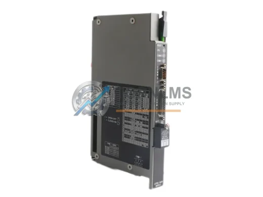
Allen-Bradley
Allen-Bradley 1771-DMC Original Industrial Spare PLC-5 Compatible
1771-DMCAllen-Bradley 1771-DMC PLC-5 original coprocessor module. Industrial spare for legacy control systems. 12-month warranty, tested before shipment.
Request availability, condition, lead time and export shipping details for 1757-SRC3.

Send this exact part number, quantity and destination country. TOPNLMS will confirm availability, condition and export lead time before quotation.
In high-availability manufacturing environments, unplanned downtime is not merely an operational inconvenience — it is a direct threat to production targets, safety compliance, and long-term equipment ROI. The Allen-Bradley 1757-SRC3 ControlLogix System Redundancy Controller is a mission-critical spare component engineered to sustain continuous system operation in redundant PLC architectures. Whether you are managing a petrochemical plant, an automotive assembly line, a water treatment facility, or a discrete manufacturing cell, maintaining a verified, original 1757-SRC3 in your spare parts inventory is a fundamental pillar of any serious preventive maintenance strategy.
The 1757-SRC3 serves as the synchronization backbone of a ControlLogix redundancy chassis pair. It coordinates real-time data mirroring between the primary and secondary controller chassis, enabling bumpless switchover in the event of a primary controller fault. This means that when a CPU fault, power interruption, or communication failure occurs on the primary side, the secondary chassis assumes control within milliseconds — with no process interruption, no data loss, and no operator intervention required. For processes where even a brief halt carries significant cost or safety risk, this capability is indispensable.
| Parameter | Specification |
|---|---|
| Part Number / SKU | 1757-SRC3 |
| Brand | Allen-Bradley (Rockwell Automation) |
| Series | ControlLogix 1757 Redundancy Series |
| Product Type | System Redundancy Controller (SRC) |
| Compatible Platform | ControlLogix 1756 Redundancy Systems |
| Compatible Controllers | 1756-L55, 1756-L61, 1756-L62, 1756-L63, 1756-L64, 1756-L65 |
| Redundancy Fiber Cable | 1757-SRM (Redundancy Module) fiber interconnect required |
| Backplane Communication | ControlLogix 1756 backplane compatible |
| Chassis Slot Requirement | Single slot, ControlLogix chassis |
| Operating Temperature | 0°C to 60°C (32°F to 140°F) |
| Storage Temperature | -40°C to 85°C |
| Relative Humidity | 5% to 95% non-condensing |
| Country of Origin | United States |
| Condition | Original / Genuine Allen-Bradley |
| Warranty | 12 Months |
| Application Environment | Industrial automation, process control, redundant PLC systems |
| Maintenance Recommendation | Inspect fiber connections and chassis backplane contacts every 12 months; replace if SRC fault LED is active |
A redundancy controller like the 1757-SRC3 does not operate in isolation. Its effectiveness is entirely dependent on the health of the surrounding ControlLogix ecosystem. During scheduled maintenance windows or unplanned shutdowns, maintenance engineers should treat the 1757-SRC3 inspection as the starting point of a broader system health audit — not the endpoint.
Begin with the redundancy fiber interconnect. The 1757-SRM Redundancy Module, which pairs with the 1757-SRC3 to manage chassis-to-chassis synchronization, relies on clean, undamaged fiber optic cables. Contaminated or bent fiber connectors are a leading cause of redundancy synchronization failures that go undetected until a switchover event exposes the fault. Inspect and clean fiber terminations at every scheduled PM interval.
Next, evaluate the power supply modules in both the primary and secondary chassis. The 1756-PA72 and 1756-PB72 ControlLogix power supplies are common companions to redundant controller configurations. A degraded power supply that has not yet tripped a fault can still introduce voltage ripple that destabilizes backplane communication — a subtle failure mode that only manifests under load. Keeping a spare 1756-PA72 or 1756-PB72 alongside your 1757-SRC3 inventory is a low-cost insurance policy against extended downtime.
I/O module integrity is equally important. In a redundant ControlLogix system, remote I/O racks connected via 1756-EN2T or 1756-EN2TR EtherNet/IP communication modules must maintain stable network connectivity to both chassis. During your inspection, verify that all 1756-EN2T modules show healthy link status LEDs and that no port has degraded to half-duplex operation. A failing communication module can cause the redundancy system to misinterpret a network fault as a controller fault, triggering unnecessary switchovers.
Relay output modules such as the 1756-OW16I are frequently overlooked during redundancy-focused maintenance. However, relay contacts in high-cycle applications wear over time, and a welded or open relay contact can mask a process fault that the redundancy system cannot compensate for. Inspect relay modules for contact resistance and cycle count during the same maintenance window as your 1757-SRC3 check.
Terminal blocks and wiring integrity within the control cabinet also deserve attention. Loose terminal connections on 1492-series terminal blocks — commonly used in ControlLogix panel builds — can introduce intermittent signal faults that generate nuisance alarms and complicate fault diagnosis. Torque-check all terminal connections and replace any discolored or corroded terminals during your PM cycle.
Finally, if your redundant ControlLogix system communicates with a DCS or SCADA layer via a 1756-DHRIO or 1756-CNB communication bridge module, verify that these modules are running current firmware and that their diagnostic counters show no accumulated communication errors. A communication bridge fault upstream of the redundancy pair can isolate the entire control node from the supervisory system, negating the operational benefit of the redundancy architecture even when the 1757-SRC3 itself is functioning correctly.
The 1757-SRC3 was introduced as part of Rockwell Automation’s ControlLogix redundancy platform to replace earlier, less capable redundancy solutions. For facilities still operating legacy redundancy configurations based on older SRC revisions or non-ControlLogix platforms, the 1757-SRC3 represents a direct upgrade path that preserves existing chassis infrastructure while delivering improved synchronization speed and fault detection capability.
One of the most significant advantages of sourcing an original 1757-SRC3 as a replacement spare is the elimination of firmware compatibility risk. Counterfeit or refurbished modules sourced from unverified channels frequently carry mismatched firmware versions that cause synchronization handshake failures during chassis pairing. An original 1757-SRC3 from a verified supplier ships with factory-baseline firmware, ensuring immediate compatibility with your existing ControlLogix controller firmware revision without requiring a field firmware update.
For maintenance teams managing aging ControlLogix redundancy systems, the 1757-SRC3 also provides a cost-effective alternative to full system migration. Rather than investing in a complete platform upgrade to a newer redundancy architecture, replacing a faulty or end-of-service-life SRC module extends the operational life of the existing system by several years — preserving the capital investment in chassis, I/O infrastructure, and application programming while restoring full redundancy capability.
Procurement teams should note that lead times for legacy Allen-Bradley redundancy components from standard distribution channels can extend to 8–16 weeks during periods of supply chain constraint. Maintaining at least one verified 1757-SRC3 spare on-site eliminates this lead time risk entirely and ensures that a redundancy module fault — which by definition means the system is operating without backup protection — can be resolved within hours rather than weeks.
Q1: What is the expected service life of the 1757-SRC3, and when should I plan for replacement?
The 1757-SRC3 does not have a fixed MTBF-based replacement interval under normal operating conditions. However, Rockwell Automation has placed the 1757 series on its End of Life product list, meaning new production has ceased. Replacement planning should begin immediately for any facility relying on this module, and at minimum one verified spare should be held in inventory. Modules showing active SRC fault LEDs, synchronization errors in the RSLogix 5000 diagnostics, or physical damage to fiber connectors should be replaced without delay.
Q2: How do I verify compatibility between the 1757-SRC3 and my existing ControlLogix controller firmware?
Compatibility is determined by the firmware revision of your 1756-series controller (e.g., 1756-L63 or 1756-L65) and the RSLogix 5000 / Studio 5000 project version. Refer to Rockwell Automation Publication 1757-UM536 for the compatibility matrix. As a general rule, the 1757-SRC3 is compatible with ControlLogix controllers running firmware v16 through v20. If your project is running a later firmware revision, consult the compatibility guide before installation.
Q3: What pre-shipment testing is performed on the 1757-SRC3?
Every 1757-SRC3 unit shipped from TOPNLMS undergoes functional verification including power-on self-test confirmation, LED status check, and physical inspection of all connectors and backplane contacts. Units are packaged in anti-static ESD bags with protective foam inserts to prevent transit damage. A 12-month warranty covers all verified defects in materials and workmanship from the date of shipment.
Q4: Can the 1757-SRC3 be installed while the system is running (hot-swap)?
No. The 1757-SRC3 requires the chassis to be powered down before installation or removal. Attempting to insert or remove the module with the chassis energized risks backplane damage and potential data corruption in the controller. Always follow Rockwell Automation’s lockout/tagout procedures and refer to Publication 1757-IN536 for installation instructions. Plan the replacement during a scheduled maintenance window to ensure a controlled, safe installation.
Allen-Bradley 1771-DMC PLC-5 original coprocessor module. Industrial spare for legacy control systems. 12-month warranty, tested before shipment.
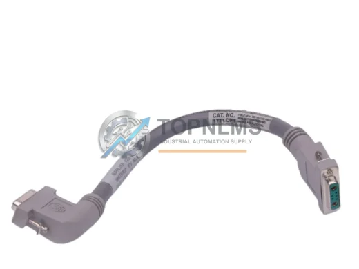
Allen-Bradley 1771-CP1 I/O Chassis Interconnect Cable replacement for PLC-5 platform. Compatible upgrade, 12-month warranty, fast global shipping from stock.

Allen-Bradley 1769-L33ERM CompactLogix 5370 L3 PLC Controller — original industrial spare, fast replacement, 12-month warranty. Verified & shipped from TOPNLMS.
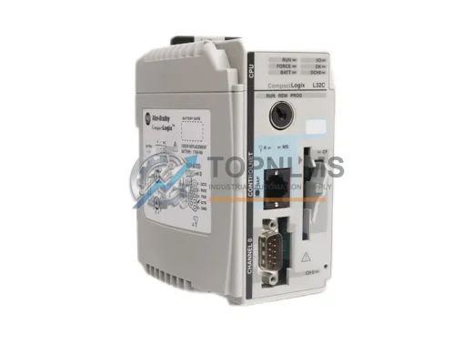
Allen-Bradley 1769-L32C CompactLogix ControlNet PLC – original industrial spare, Series C compatible, 12-month warranty, fast global shipping. Reduce downtime now.
Click Quote This Model and the Part Number field will auto-fill with 1757-SRC3.