
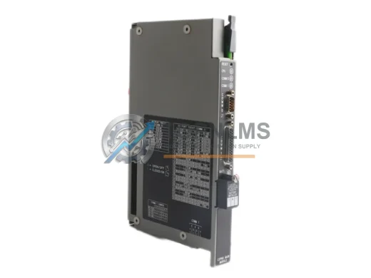
Allen-Bradley
Allen-Bradley 1771-DMC Original Industrial Spare PLC-5 Compatible
1771-DMCAllen-Bradley 1771-DMC PLC-5 original coprocessor module. Industrial spare for legacy control systems. 12-month warranty, tested before shipment.
Request availability, condition, lead time and export shipping details for 1756-RM2.
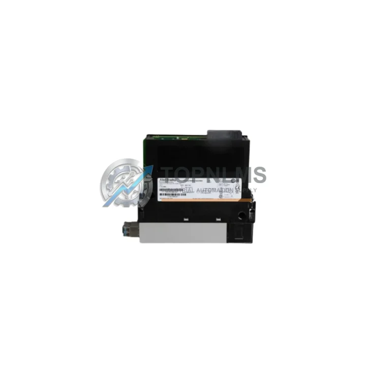
Send this exact part number, quantity and destination country. TOPNLMS will confirm availability, condition and export lead time before quotation.
The Allen-Bradley 1756-RM2 Enhanced Redundancy Module is a cornerstone component for any facility operating a ControlLogix 1756-series redundant control system. In process industries, utilities, oil & gas, and advanced discrete manufacturing, unplanned downtime is not merely an inconvenience — it translates directly into lost production, safety risks, and costly emergency maintenance. Stocking a verified original 1756-RM2 spare is one of the most impactful decisions a maintenance engineer or reliability manager can make to protect system uptime and extend the operational life of an existing ControlLogix platform.
The 1756-RM2 manages the synchronization and switchover logic between a primary and secondary ControlLogix chassis, enabling bumpless transfer in the event of a controller fault, power loss, or scheduled maintenance window. Its role is not passive — it actively monitors chassis health, coordinates data synchronization across the redundancy link, and executes switchover in milliseconds. A degraded or failed 1756-RM2 eliminates the redundancy protection your system was designed to provide, leaving the entire control loop exposed to single-point failure. Maintaining a tested, ready-to-deploy spare eliminates this risk entirely.
| Parameter | Specification |
|---|---|
| Part Number / SKU | 1756-RM2 |
| Brand | Allen-Bradley (Rockwell Automation) |
| Series | ControlLogix 1756 |
| Module Type | Enhanced Redundancy Module |
| Redundancy Link | Fiber-optic, dual-port (primary & secondary chassis) |
| Switchover Time | Bumpless transfer, typically <10 ms |
| Compatible Chassis | 1756-A4, 1756-A7, 1756-A10, 1756-A13, 1756-A17 |
| Compatible Controllers | 1756-L71, 1756-L72, 1756-L73, 1756-L74, 1756-L75 |
| Firmware Compatibility | RSLogix 5000 / Studio 5000 Logix Designer |
| Power Consumption | Supplied via 1756 chassis backplane |
| Operating Temperature | 0 °C to 60 °C (32 °F to 140 °F) |
| Relative Humidity | 5% to 95% non-condensing |
| Installation | 1756 chassis slot (dedicated redundancy slot) |
| Origin | United States |
| Condition | Original, genuine Allen-Bradley |
| Warranty | 12 Months |
| Pre-shipment Testing | Full functional verification prior to dispatch |
A robust preventive maintenance program for a ControlLogix redundant system extends well beyond the 1756-RM2 itself. During scheduled outages or annual control cabinet inspections, maintenance teams should treat the redundancy module replacement as part of a broader system health review. When technicians open the control cabinet to inspect or replace the 1756-RM2, it is best practice to simultaneously verify the condition of the 1756-L73 or 1756-L75 ControlLogix controllers in both the primary and secondary chassis — controller firmware should be synchronized and battery backup modules such as the 1756-BATA should be checked for charge state and replaced on a scheduled cycle.
The redundancy fiber-optic link cables connecting the two chassis are a frequently overlooked failure point. Inspect and, where necessary, replace the 1756-RMC1 or 1756-RMC3 fiber-optic redundancy cables during the same maintenance window. Damaged or contaminated fiber connectors can cause intermittent synchronization faults that are difficult to diagnose under load. While the chassis is open, inspect the 1756-PA75 or 1756-PB75 power supply modules in both chassis — power supply degradation is a leading cause of unexpected redundancy switchovers and should be addressed proactively.
For I/O integrity, verify the health of any 1756-IB16 digital input modules and 1756-OB16E digital output modules installed in the chassis. Loose terminal connections, worn field wiring, or aging I/O modules can introduce signal noise that triggers nuisance faults. If the system includes analog process control loops, inspect 1756-IF8 analog input modules for calibration drift. Communication infrastructure should also be reviewed: 1756-EN2T EtherNet/IP communication modules should be checked for firmware currency and network health statistics, as communication module faults can disrupt the HMI and SCADA visibility that operators depend on during a redundancy switchover event.
Finally, for facilities running older ControlLogix installations, consider auditing the 1756-DNB DeviceNet Bridge modules or 1756-CN2 ControlNet modules if legacy fieldbus networks are still in use. Maintaining a small buffer stock of these associated modules alongside the 1756-RM2 ensures that a single maintenance visit can resolve multiple aging components simultaneously, minimizing future unplanned outages.
The 1756-RM2 is the direct replacement for the earlier 1756-RM redundancy module, offering enhanced synchronization performance, improved diagnostics, and broader controller compatibility. Facilities still operating systems built around the original 1756-RM can upgrade to the 1756-RM2 without chassis replacement, preserving the existing 1756-series infrastructure investment while gaining access to improved redundancy features supported in current Studio 5000 firmware releases.
For plants managing aging ControlLogix systems originally commissioned in the early 2000s, the 1756-RM2 provides a clear path to extending system life by 5–10 years without the capital expenditure of a full DCS or PLC platform migration. The module is fully compatible with current Rockwell Automation firmware and engineering tools, meaning existing ladder logic, function block programs, and HMI configurations require no modification. This compatibility dramatically reduces the engineering risk and commissioning time associated with a spare part replacement, allowing maintenance teams to execute a controlled switchover and module swap during a planned outage window — often within a single shift.
Stocking the 1756-RM2 as a strategic spare also supports emergency response scenarios. In the event of an unplanned redundancy module failure, having a tested unit on the shelf reduces mean time to repair (MTTR) from days (lead time for emergency procurement) to hours (time to physically swap and recommission the module). For facilities with contractual uptime obligations or safety-instrumented systems, this reduction in MTTR has direct financial and compliance value.
Q1: Is the 1756-RM2 compatible with all ControlLogix 1756-series controllers?
The 1756-RM2 is compatible with the L7x-series ControlLogix controllers (1756-L71 through 1756-L75) and requires Studio 5000 Logix Designer for configuration. It is not compatible with the older L6x-series controllers, which require the original 1756-RM. Please verify your controller catalog number before ordering. If you are unsure, contact us with your existing controller part number and we will confirm compatibility.
Q2: What pre-shipment testing is performed on the 1756-RM2?
Every 1756-RM2 unit shipped from TOPNLMS undergoes full functional verification prior to dispatch, including power-on self-test, redundancy link port integrity check, and firmware version confirmation. Units are packaged in anti-static protective packaging with inspection documentation. A 12-month warranty is provided from the date of shipment, covering manufacturing defects and functional failures under normal operating conditions.
Q3: How should I manage spare part inventory for a ControlLogix redundant system?
Best practice for critical redundant systems is to maintain at minimum one 1756-RM2 spare per redundant pair in your facility. For multi-unit installations or facilities with long procurement lead times, a ratio of one spare per two to three installed units is recommended. Spares should be stored in a climate-controlled environment, inspected annually, and rotated into service on a scheduled basis to prevent shelf degradation. Pairing the 1756-RM2 spare with controller battery modules and fiber-optic link cables in a dedicated redundancy spare kit simplifies emergency response logistics.
Q4: Can the 1756-RM2 be replaced while the system is running?
The 1756-RM2 is not designed for hot-swap replacement while both chassis are in active redundant operation. Replacement should be performed during a planned maintenance window with the secondary chassis taken offline in a controlled manner. The primary chassis continues to control the process during the replacement. After the new module is installed and the secondary chassis is brought back online, the system will automatically re-synchronize. Full recommissioning and switchover testing should be performed before returning the system to normal redundant operation. Our technical support team is available to assist with replacement planning.
Allen-Bradley 1771-DMC PLC-5 original coprocessor module. Industrial spare for legacy control systems. 12-month warranty, tested before shipment.
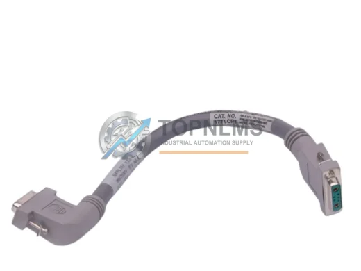
Allen-Bradley 1771-CP1 I/O Chassis Interconnect Cable replacement for PLC-5 platform. Compatible upgrade, 12-month warranty, fast global shipping from stock.

Allen-Bradley 1769-L33ERM CompactLogix 5370 L3 PLC Controller — original industrial spare, fast replacement, 12-month warranty. Verified & shipped from TOPNLMS.
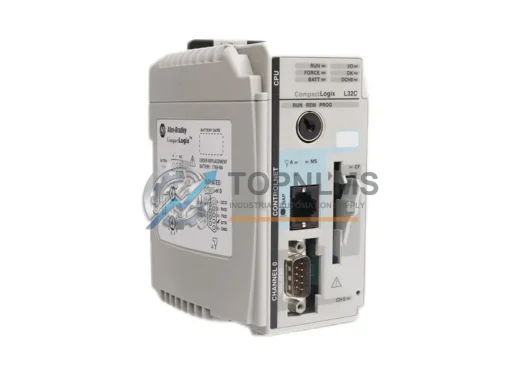
Allen-Bradley 1769-L32C CompactLogix ControlNet PLC – original industrial spare, Series C compatible, 12-month warranty, fast global shipping. Reduce downtime now.
Click Quote This Model and the Part Number field will auto-fill with 1756-RM2.