
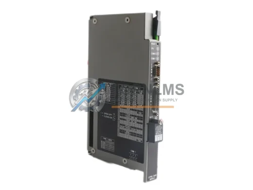
Allen-Bradley
Allen-Bradley 1771-DMC Original Industrial Spare PLC-5 Compatible
1771-DMCAllen-Bradley 1771-DMC PLC-5 original coprocessor module. Industrial spare for legacy control systems. 12-month warranty, tested before shipment.
Request availability, condition, lead time and export shipping details for 1756-RM/B.
Send this exact part number, quantity and destination country. TOPNLMS will confirm availability, condition and export lead time before quotation.
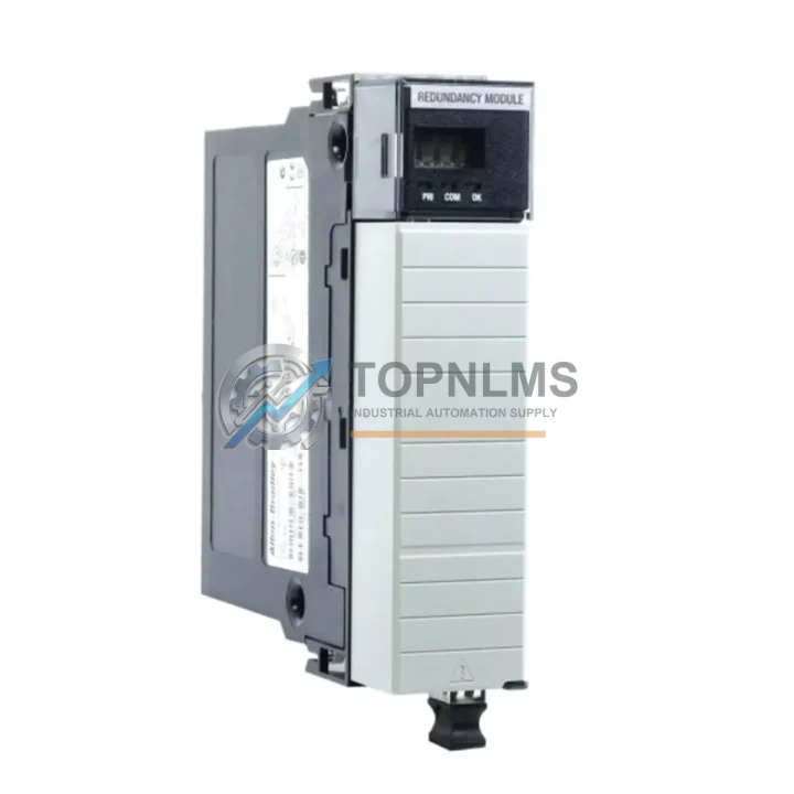
The Allen-Bradley 1756-RM/B is a critical redundancy module within the Rockwell Automation ControlLogix 1756 platform, engineered to ensure continuous process availability in demanding industrial environments. For maintenance engineers and procurement teams managing aging control infrastructure, sourcing a verified original 1756-RM/B spare is not merely a purchasing decision — it is a risk management strategy. Unplanned downtime in process manufacturing, oil and gas, water treatment, or automotive assembly can cost tens of thousands of dollars per hour. A pre-qualified, shelf-ready 1756-RM/B eliminates the most dangerous variable in any emergency repair scenario: lead time.
The 1756-RM/B operates as the backbone of a ControlLogix redundancy pair, synchronizing program data, I/O state, and communication status between a primary and secondary chassis in real time. When the primary controller detects a fault, the 1756-RM/B orchestrates a bumpless switchover — typically within one controller scan — ensuring that field devices, actuators, and HMI displays experience no perceptible interruption. This capability is indispensable in SIL-rated safety loops, continuous batch processes, and any application where a cold restart would trigger regulatory reporting or product loss.
| Parameter | Specification |
|---|---|
| Part Number | 1756-RM/B |
| Series | ControlLogix 1756 Series B |
| Module Type | Redundancy Module (RM) |
| Compatibility | ControlLogix 1756 chassis; pairs with 1756-L6x / 1756-L7x / 1756-L8x controllers |
| Redundancy Fiber Cable | Requires 1756-RMC / 1756-RMCT fiber cable (sold separately) |
| Switchover Time | Bumpless, within one controller scan cycle |
| Backplane Current Draw | 1.0 A @ 5 VDC; 3.0 mA @ 24 VDC |
| Operating Temperature | 0 °C to 60 °C (32 °F to 140 °F) |
| Storage Temperature | -40 °C to 85 °C |
| Relative Humidity | 5% to 95% non-condensing |
| Chassis Slot Width | Single slot, 1756 ControlLogix chassis |
| Firmware Compatibility | RSLogix 5000 / Studio 5000 Logix Designer |
| Certifications | UL, CE, cUL |
| Origin | Original Allen-Bradley / Rockwell Automation |
| Warranty | 12 Months — tested before shipment |
| Condition | Original, surplus new / refurbished-to-spec |
A scheduled inspection of your ControlLogix redundancy system should never be limited to the 1756-RM/B module alone. The redundancy architecture depends on the health of every component in both the primary and secondary chassis. During a planned maintenance window, technicians should simultaneously verify the status of the 1756-L73 or 1756-L74 ControlLogix controller in each chassis — firmware version alignment between primary and secondary controllers is a prerequisite for stable redundancy operation and is a common root cause of switchover failures that go undetected until a fault event occurs.
The fiber interconnect between the two redundancy modules is equally critical. The 1756-RMC or 1756-RMCT fiber cable should be inspected for bend radius violations, connector contamination, and optical signal integrity. A degraded fiber link can cause the redundancy pair to desynchronize silently, leaving the system in a non-redundant state without triggering an obvious alarm. Keeping a spare fiber cable alongside the 1756-RM/B in your maintenance inventory is a low-cost insurance policy against this failure mode.
Power integrity across both chassis is another area that warrants attention during the same inspection cycle. The 1756-PA75 or 1756-PB75 power supply module should be load-tested and its output voltage verified under full backplane load. A marginal power supply that passes a no-load bench test may still cause intermittent resets under production conditions. If your facility operates dual-feed power to the redundancy chassis, the 1756-PA75R redundant power supply configuration should also be reviewed for proper load sharing.
I/O integrity is the third pillar of a complete redundancy audit. 1756-IB16 digital input modules and 1756-OB16E digital output modules should be checked for blown fuse indicators, field wiring continuity, and correct module configuration in the I/O tree. Any module reporting a partial fault should be flagged for replacement before the next planned outage, not after an unplanned one. For analog process loops, the 1756-IF16 analog input module calibration drift should be verified against known reference signals, particularly in temperature-critical or flow-metering applications.
Communication infrastructure supporting the redundancy system also deserves a place on the inspection checklist. The 1756-EN2T EtherNet/IP communication module handles HMI, SCADA, and historian connectivity; a failed EN2T can isolate the controller from the supervisory layer even when the redundancy pair itself is healthy. Similarly, if your plant uses DeviceNet or ControlNet field buses, the corresponding 1756-DNB or 1756-CNB communication modules should be verified for active connection counts and error log history.
Finally, the chassis backplane itself — the 1756-A10 or 1756-A17 ControlLogix chassis — should be inspected for slot connector oxidation, physical damage, and proper grounding. A corroded backplane connector can introduce intermittent communication errors that are extremely difficult to diagnose under production pressure. Maintaining a documented baseline of module slot assignments and firmware versions for both the primary and secondary chassis transforms a reactive maintenance team into a proactive one.
The 1756-RM/B (Series B) supersedes the earlier 1756-RM (Series A), offering improved synchronization performance and broader firmware compatibility with the Studio 5000 Logix Designer environment. For facilities still operating Series A redundancy modules, a like-for-like upgrade to the 1756-RM/B is the lowest-risk modernization path: the physical form factor, chassis slot footprint, and fiber cable interface are identical, requiring no chassis modification or I/O rewiring. The upgrade delivers measurable improvements in switchover reliability and expands compatibility with current-generation 1756-L8x Logix 5580 controllers.
For plants operating legacy systems where the original 1756-RM/B is no longer available through standard distribution channels, sourcing a verified original surplus unit from a specialist supplier is significantly preferable to attempting a cross-brand substitution. Third-party or counterfeit redundancy modules introduce unpredictable firmware handshake behavior that can corrupt the synchronization state and cause both controllers to fault simultaneously — the exact failure mode the redundancy architecture is designed to prevent. Every 1756-RM/B shipped from TOPNLMS undergoes functional verification, firmware version documentation, and a 12-month warranty covering both parts and workmanship.
For facilities planning a longer-term migration toward the ControlLogix 5580 platform, the 1756-RM/B remains fully compatible with mixed-generation chassis configurations during the transition period, allowing a phased upgrade strategy that avoids a single high-risk cutover event. This compatibility bridge significantly reduces the capital expenditure and project risk associated with control system modernization in brownfield industrial sites.
Q1: Is the 1756-RM/B compatible with both 1756-L6x and 1756-L7x series controllers?
Yes. The 1756-RM/B is compatible with ControlLogix L6x (Logix 5563/5564/5565/5571/5572/5573/5574/5575) and L7x (Logix 5571/5572/5573/5574/5575/5576/5577) controllers, as well as the current-generation L8x Logix 5580 series, subject to firmware version alignment between the primary and secondary chassis. Firmware version matching is mandatory for stable redundancy operation.
Q2: What testing is performed before shipment?
Each 1756-RM/B unit is powered on, backplane communication is verified, and the module firmware version is documented prior to packaging. Units are shipped with anti-static protection and impact-resistant packaging. A 12-month warranty covering manufacturing defects and functional failure is included with every order. Test records are available upon request for quality-critical procurement processes.
Q3: How should I validate compatibility before installing a replacement 1756-RM/B in a live system?
Before installation, confirm that the replacement module’s series letter (Series B) matches your existing redundancy module. Verify that the firmware version supported by the replacement unit is compatible with the controller firmware currently running in both chassis. It is strongly recommended to perform the physical swap during a planned maintenance window with the redundancy pair in a known-healthy state, and to use RSLogix 5000 / Studio 5000 to monitor the redundancy status display during the first several scan cycles after installation.
Q4: What is your inventory and lead time policy for the 1756-RM/B?
We maintain stock of the 1756-RM/B to support emergency maintenance scenarios. Standard orders are processed and shipped within 1–3 business days. For facilities managing critical infrastructure, we recommend holding at least one 1756-RM/B as an on-site cold spare, given that the module is a single point of failure for the entire redundancy architecture. Bulk procurement pricing is available for MRO inventory programs — contact our team for a formal quotation.
Allen-Bradley 1771-DMC PLC-5 original coprocessor module. Industrial spare for legacy control systems. 12-month warranty, tested before shipment.
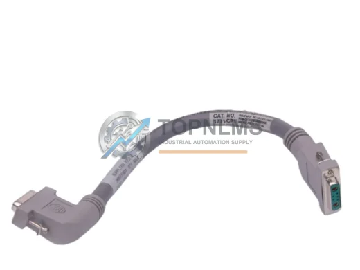
Allen-Bradley 1771-CP1 I/O Chassis Interconnect Cable replacement for PLC-5 platform. Compatible upgrade, 12-month warranty, fast global shipping from stock.

Allen-Bradley 1769-L33ERM CompactLogix 5370 L3 PLC Controller — original industrial spare, fast replacement, 12-month warranty. Verified & shipped from TOPNLMS.
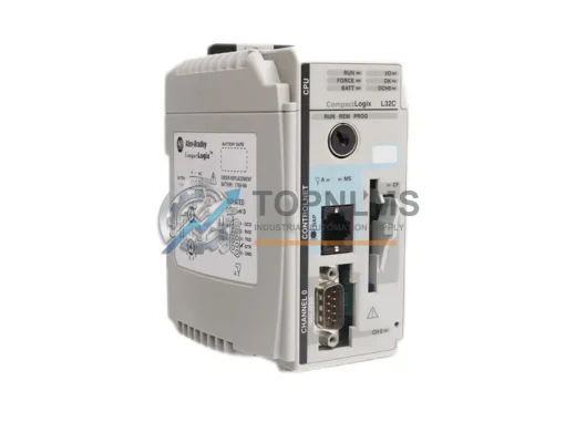
Allen-Bradley 1769-L32C CompactLogix ControlNet PLC – original industrial spare, Series C compatible, 12-month warranty, fast global shipping. Reduce downtime now.
Click Quote This Model and the Part Number field will auto-fill with 1756-RM/B.