Product Overview
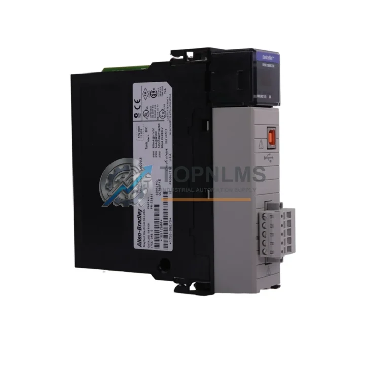
Allen-Bradley 1756-DNB Replacement for ControlLogix 1756: Smooth Migration from Legacy DeviceNet Systems
The Allen-Bradley 1756-DNB DeviceNet Scanner Module is a critical communication bridge within the Rockwell Automation ControlLogix 1756 platform, enabling seamless integration between ControlLogix controllers and DeviceNet field devices such as variable-frequency drives, smart sensors, valve manifolds, and distributed I/O nodes. As legacy DeviceNet infrastructure ages and original 1756-DNB units approach end-of-life or become increasingly difficult to source, facilities engineers and procurement teams face mounting pressure to secure verified replacement units that preserve existing wiring, programming, and system architecture without triggering a full-scale control system overhaul.
TOPNLMS supplies the 1756-DNB as a direct drop-in replacement for ControlLogix 1756 chassis applications. Each unit is sourced from verified supply channels, pre-shipment tested, and backed by a 12-month warranty. Whether you are managing an emergency breakdown, building a critical-spare inventory, or executing a phased modernization program, the 1756-DNB available through TOPNLMS is ready to ship from Xiamen with full export documentation.
Compatibility Comparison Table
| Parameter |
Legacy / Outgoing Unit |
1756-DNB (Replacement) |
| Module Type |
DeviceNet Scanner (older firmware revisions) |
DeviceNet Scanner – ControlLogix 1756 Series |
| Chassis Compatibility |
ControlLogix 1756 chassis (any slot) |
ControlLogix 1756 chassis (any slot) – direct fit |
| Communication Protocol |
DeviceNet (CAN-based, ISO 11898) |
DeviceNet (CAN-based, ISO 11898) – fully compatible |
| Network Topology |
Trunk-line/drop-line, multi-drop |
Trunk-line/drop-line, multi-drop – no rewiring required |
| Max Nodes Supported |
Up to 63 nodes per network |
Up to 63 nodes per network |
| Data Rates |
125 / 250 / 500 Kbps |
125 / 250 / 500 Kbps – selectable, backward compatible |
| Wiring Interface |
5-pin open-style DeviceNet connector |
5-pin open-style DeviceNet connector – identical pinout |
| Power Consumption |
Backplane powered via 1756 chassis |
Backplane powered via 1756 chassis – no external PSU needed |
| Programming Environment |
RSNetWorx for DeviceNet / Studio 5000 |
RSNetWorx for DeviceNet / Studio 5000 – no re-programming required |
| Firmware Upgrade |
Varies by revision |
Upgradeable via ControlFLASH – latest firmware available |
| Physical Dimensions |
Standard 1756 single-slot module |
Standard 1756 single-slot module – no panel modification |
| Replacement Recommendation |
Direct swap – no hardware or software changes required |
✔ Verified drop-in replacement |
| Warranty |
— |
12-Month Warranty from TOPNLMS |
Seamless Upgrade Solutions
A successful 1756-DNB migration rarely involves a single module swap in isolation. In practice, the DeviceNet scanner sits within a broader ControlLogix architecture that must be evaluated holistically to ensure continuity of operations. During the replacement process, engineers commonly audit the 1756-L71 or 1756-L74 ControlLogix controller to confirm firmware compatibility with the replacement scanner module, since mismatched firmware revisions between the CPU and communication modules can cause unexpected faults on first power-up.
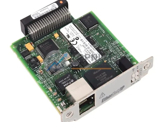
The 1756-EN2T EtherNet/IP communication module, typically installed in the same chassis, should be verified for correct routing table entries if the DeviceNet network is accessed remotely via RSLinx or Studio 5000 online diagnostics. In multi-chassis systems connected via the 1756-RM redundancy module, the replacement 1756-DNB must be installed symmetrically in both primary and secondary chassis to maintain redundancy integrity.
On the field side, DeviceNet trunk cables terminated with 1485C-P1A5-C or equivalent DeviceNet media connectors should be inspected for impedance continuity before reconnecting to the replacement scanner. Termination resistors at both ends of the trunk must remain in place; failure to verify this is a common cause of CAN bus errors after module replacement. If the existing network includes 1794-ADN FLEX I/O DeviceNet adapters or 1734-ADN POINT I/O DeviceNet adapters, their node addresses and EDS files should be backed up prior to the swap and re-commissioned using RSNetWorx for DeviceNet after the new 1756-DNB is seated.
For facilities running mixed-protocol control cabinets, the replacement process is also an appropriate time to evaluate whether the 1756-ENBT or 1756-EN2TR modules require firmware updates to align with the current Studio 5000 project revision. Power supply integrity is equally important: the 1756-PA75 or 1756-PB75 chassis power supply should be load-tested to confirm it can sustain the full backplane current draw after the new module is installed, particularly in fully populated 17-slot or 10-slot chassis configurations.
Where the migration is part of a broader modernization initiative — for example, transitioning from a legacy PLC-5 or SLC 500 system that previously used the 1771-SDN DeviceNet scanner — the 1756-DNB serves as the natural successor, retaining DeviceNet field device compatibility while delivering the processing power and diagnostics of the ControlLogix platform. In these scenarios, I/O mapping and ladder logic conversion should be completed in Studio 5000 before the physical cutover to minimize downtime during the transition window.
Retrofit Guidance FAQ
Q: Do I need to rewire the DeviceNet trunk when replacing the 1756-DNB?
No. The 1756-DNB uses a standard 5-pin open-style DeviceNet connector with identical pinout (V+, CAN_H, Shield, CAN_L, V−). The existing trunk cable and drop lines connect directly to the replacement module without modification. Verify termination resistors (121 Ω) are present at both ends of the trunk before powering up.
Q: Will my existing RSNetWorx for DeviceNet configuration work with the replacement module?
Yes. The 1756-DNB replacement retains the same DeviceNet node address (MAC ID) configuration. After seating the module, upload the existing network configuration from RSNetWorx, verify node addresses, and download to the new scanner. No EDS file changes are required for standard field devices already on the network.
Q: Is the Studio 5000 / RSLogix 5000 project compatible without modification?
In most cases, yes. The I/O tree in Studio 5000 references the 1756-DNB by slot number and module profile. As long as the replacement module occupies the same chassis slot, the controller will recognize it automatically on the next download or go-online operation. If the firmware revision differs significantly, a ControlFLASH update may be required before the module is accepted by the controller.
Q: What are the physical space requirements in the control cabinet?
The 1756-DNB occupies a single slot in any ControlLogix 1756 chassis (4-, 7-, 10-, 13-, or 17-slot). No additional DIN rail space, external power supply, or panel cutout is required. The module is backplane-powered and draws current from the 1756 chassis power supply.
Q: How do I handle the transition if the original module has a fault and cannot be read?
If the original 1756-DNB is faulted and cannot be interrogated, retrieve the DeviceNet network configuration from the RSNetWorx project file stored on the engineering workstation. Re-commission the network using RSNetWorx after installing the replacement module, verifying each node’s MAC ID, data rate, and I/O connection parameters against the original project documentation.
Q: Can the 1756-DNB replacement be used in a redundant ControlLogix system?
Yes, provided the replacement module is installed in both the primary and secondary chassis in identical slot positions. The 1756-RM redundancy module manages switchover; the DeviceNet scanner must be present and healthy in both chassis for redundancy to function correctly.
Warranty Assurance
Every 1756-DNB unit shipped by TOPNLMS is covered by a 12-month warranty from the date of delivery. Prior to shipment, each module undergoes functional verification including backplane communication checks, DeviceNet port integrity testing, and LED status confirmation. Units that do not pass pre-shipment inspection are not dispatched.
In the event of a warranty claim, TOPNLMS provides a replacement unit or full refund based on the customer’s preference and the nature of the fault. Our after-sales response target is within 24 hours of claim submission. Warranty coverage includes manufacturing defects, communication failures, and hardware faults under normal operating conditions. Physical damage caused by incorrect installation, overvoltage, or environmental factors outside the module’s rated specifications is excluded.
For procurement teams requiring documentation, TOPNLMS can provide a certificate of conformance, packing list, and commercial invoice with HS code declaration for customs clearance. Express shipping via DHL, FedEx, or UPS is available for urgent replacement orders, with typical transit times of 3–7 business days to most international destinations.
To place an order, request a quotation, or verify current stock availability, contact the TOPNLMS sales team directly:
- Email: [email protected]
- Phone / WhatsApp: +86 18359293191
- Website: https://topnlms.com
© 2026 TOPNLMS. All rights reserved. Original Source: https://topnlms.com | Contact: [email protected] | +86 18359293191