ABB
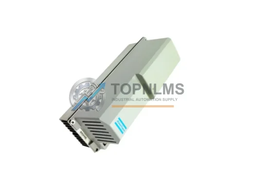
ABB 3HAB8101-19 DCQC545A Replacement for DCS600
3HAB8101-19-DCQC545AABB 3HAB8101-19 DCQC545A drop-in replacement for DCS600 DC drives. Wiring-compatible, Profibus/DDCS ready, 12-month warranty. Fast global shipping from TOPNLMS.
Request availability, condition, lead time and export shipping details for 3AFE64547992.
Send this exact part number, quantity and destination country. TOPNLMS will confirm availability, condition and export lead time before quotation.
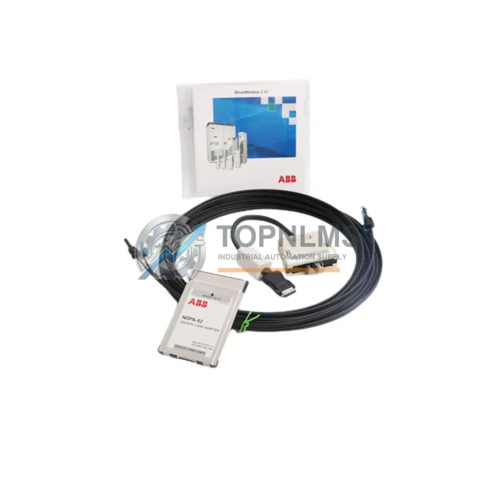
The ABB 3AFE64547992 Drive Service Field Kit is the factory-recommended commissioning and diagnostics solution for engineers undertaking a controlled migration from legacy ABB AC drive platforms to the current ACS800 and ACS600 series. Whether you are retiring an aging ACS400, decommissioning an ACS550 installation, or consolidating a multi-drive cabinet that still runs older ACS200 or ACS300 units, this kit provides the hardware interface, diagnostic tooling, and field documentation required to execute a smooth, low-downtime transition.
Industrial facilities operating continuous processes — including pulp and paper lines, water treatment stations, HVAC central plants, and conveyor-driven assembly systems — cannot afford extended drive outages. The 3AFE64547992 kit is engineered to reduce commissioning time by providing pre-configured interface adapters and structured diagnostic routines that align directly with the ACS800 and ACS600 parameter architecture. Technicians familiar with the legacy DriveWindow or DriveMonitor toolchain will find the kit’s communication interface immediately recognizable, shortening the learning curve during live retrofits.
| Parameter | Legacy Platform (ACS200 / ACS300 / ACS400) | Target Platform (ACS600 / ACS800) | 3AFE64547992 Compatibility |
|---|---|---|---|
| Communication Interface | RS-232 / RS-485 (proprietary) | DDCS / RDCO / Fieldbus Adapter | ✔ Bridging adapter included |
| Parameter Backup | Manual export via DriveMonitor | DriveWindow Light / Drive Composer | ✔ Compatible with both toolchains |
| Control Wiring (I/O) | Terminal block X1 (24 VDC logic) | Terminal block X1/X2 (24 VDC logic) | ✔ Direct pin-compatible for standard I/O |
| Fieldbus Protocol | Modbus RTU / Profibus DP (optional) | Profibus DP / DeviceNet / PROFINET (via adapter) | ✔ Protocol mapping guide included |
| Mounting / Form Factor | Frame R1–R6 (wall or cabinet) | Frame R1–R8 (wall or cabinet) | ✔ No cabinet modification required for R1–R6 |
| Power Supply | 230 VAC / 400 VAC input | 230 VAC / 400 VAC / 690 VAC input | ✔ Supply voltage unchanged for standard frames |
| Diagnostic Routine | LED fault codes only | Full fault history + real-time monitoring | ✔ Diagnostic cable and software key included |
| Warranty Coverage | N/A (end-of-life) | 12-Month Warranty | ✔ 12-Month Warranty on this kit |
A successful ACS800 or ACS600 migration rarely involves a single component swap. In practice, field engineers coordinate the replacement of several interdependent subsystems simultaneously. The 3AFE64547992 kit is most commonly deployed alongside the RDCO-02C DDCS communication module, which provides the fiber-optic link between the ACS800 inverter unit and the system-level DCS or PLC. Where the legacy installation used a standalone Profibus DP adapter such as the RPBA-01, the kit’s protocol mapping documentation allows engineers to reconfigure the ACS800’s fieldbus parameters without rewriting the upstream PLC program on the ABB AC500 controller or a third-party Siemens S7-300 rack.
Control cabinet space is a frequent constraint during retrofits. The ACS800’s compact frame sizes — particularly the R2 and R3 variants — allow direct substitution into existing DIN-rail or back-panel arrangements previously occupied by ACS400 units, provided the ACS800 mounting bracket adapter kit is used. Technicians should also verify that the existing JCU-01 or JCU-02 control unit firmware is updated to the latest revision before commissioning, as older firmware versions may not recognize the 3AFE64547992 diagnostic interface correctly.
On the I/O side, installations that relied on a dedicated RAIO-01 analog I/O extension module or an RDIO-01 digital I/O module can retain these accessories without rewiring, since the ACS800 and ACS600 share the same slot-based I/O architecture. For sites where signal isolation is required between the drive’s analog reference inputs and the process controller, a DIN-rail signal isolator (e.g., Phoenix Contact MINI MCR series) is recommended as a supplementary component. Finally, where the legacy system used a standalone CDP312R control panel for local speed reference and fault acknowledgment, the same panel connects directly to the ACS800 via the standard RJ-45 panel bus port — no adapter required.
Q: Can I reuse my existing control wiring when replacing an ACS400 with an ACS800?
A: In most cases, yes. The ACS800’s standard I/O terminal block uses the same 24 VDC logic levels and the same functional pin assignments (DI1–DI6, AI1–AI2, AO1–AO2, RO1–RO3) as the ACS400. The 3AFE64547992 kit includes a wiring cross-reference chart that maps legacy terminal designations to ACS800 equivalents, allowing technicians to verify compatibility before disconnecting any field wiring.
Q: Do I need to modify my PLC program after the drive replacement?
A: If the upstream controller communicates via Modbus RTU or Profibus DP and the drive’s node address and baud rate are preserved, no PLC program changes are required. The kit’s protocol mapping guide covers parameter-by-parameter equivalence between ACS400/ACS550 and ACS800 fieldbus configurations, enabling a like-for-like substitution at the network layer.
Q: How do I handle the physical size difference between the old and new drive frames?
A: Frame R1 through R4 ACS800 units are dimensionally similar to their ACS400 counterparts. For R5 and above, a cabinet extension panel or a revised back-plate layout may be required. The kit includes dimensional comparison drawings for the most common frame pairings.
Q: What commissioning steps are specific to the 3AFE64547992 kit?
A: After mechanical installation and wiring verification, connect the diagnostic cable from the kit to the ACS800’s PC tool port. Launch Drive Composer or DriveWindow Light, run the guided startup wizard, and confirm motor nameplate data, control macro selection, and fieldbus node configuration. The kit’s checklist covers all mandatory commissioning steps per ABB’s standard startup procedure.
Q: Is the kit compatible with ACS600 installations as well?
A: Yes. The 3AFE64547992 kit supports both ACS800 and ACS600 platforms. The diagnostic interface and parameter backup routines are compatible with the ACS600’s NAMC control board architecture, and the kit includes ACS600-specific wiring notes for DDCS and analog I/O configurations.
Every ABB 3AFE64547992 Drive Service Field Kit supplied by TOPNLMS is covered by a 12-month warranty from the date of shipment. Prior to dispatch, each kit undergoes a functional inspection that verifies the integrity of the diagnostic cable, the communication adapter, and all included documentation. Units that fail inspection are quarantined and not shipped.
In the event of a warranty claim, TOPNLMS provides a direct replacement unit dispatched within 3 business days of claim confirmation — no return-merchandise-authorization delays. Our after-sales team is reachable via email at [email protected] or by phone at +86 18359293191 for technical pre-sales consultation, compatibility verification, and post-installation support.
Stock is maintained in our Xiamen warehouse, enabling same-day dispatch for orders confirmed before 15:00 CST. Express international shipping via DHL, FedEx, or UPS is available to minimize lead time for urgent replacement scenarios. A packing list, test record, and certificate of conformity are included with every shipment to support incoming inspection at your facility.
ABB 3HAB8101-19 DCQC545A drop-in replacement for DCS600 DC drives. Wiring-compatible, Profibus/DDCS ready, 12-month warranty. Fast global shipping from TOPNLMS.
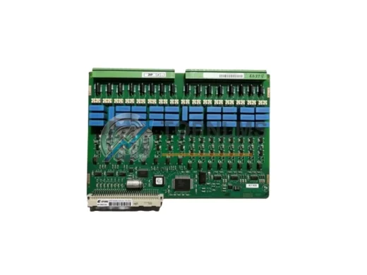
ABB 3BHL000986P3001 original spare drive control board for ACS2000 & ACS6000 medium-voltage drives. Fast shipping, tested, 12-month warranty. Industrial replacement.
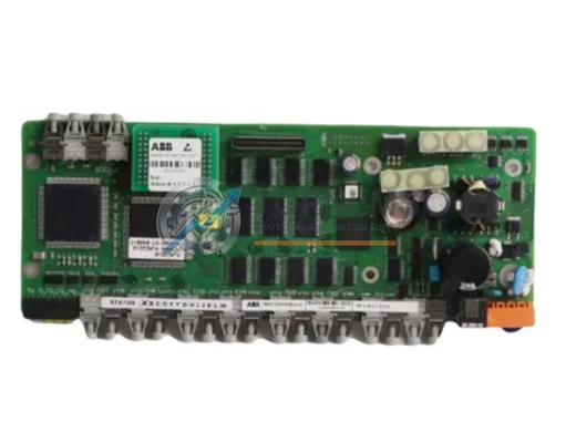
ABB 3BHE036130R0101 GDC806B Gate Drive Control Card for ACS6000 MV drives. Original OEM spare, pre-shipment tested, 12-month warranty, worldwide shipping.
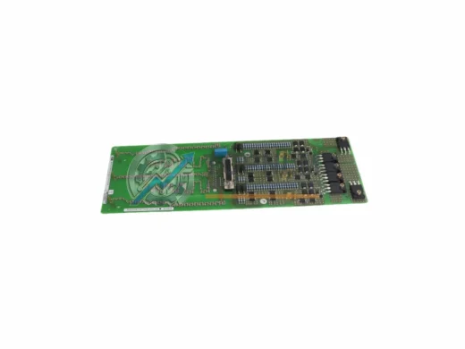
ABB 3BHE026284R0105 UAD215 A105 converter board for ACS1000/ACS6000 drives. Drop-in replacement, 12-month warranty, tested, fast global shipping from stock.
Click Quote This Model and the Part Number field will auto-fill with 3AFE64547992.