Product Overview
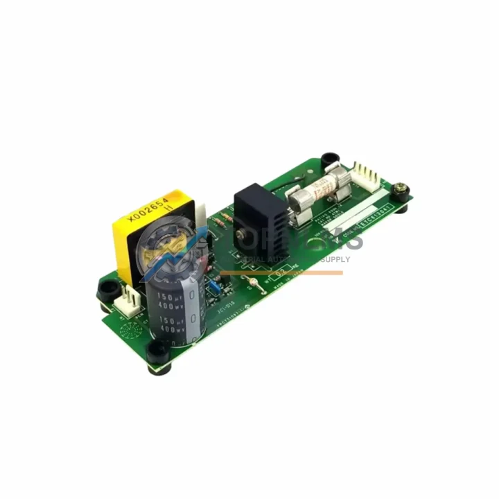
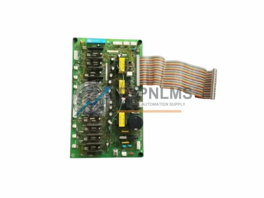
YASKAWA YPCT31097-1-0 ETC613040 Varispeed Replacement & Upgrade Solution for G5 Series
When a legacy YASKAWA Varispeed G5 series AC drive reaches end-of-life or its control board fails in service, production downtime becomes the immediate priority. The YASKAWA YPCT31097-1-0 (ETC613040) control board is the direct replacement and upgrade solution for G5-series inverter drives, restoring full drive functionality without requiring a complete drive chassis swap or PLC program rewrite. This page is designed to help maintenance engineers, procurement teams, and system integrators evaluate this board as a drop-in or migration-path replacement within existing Varispeed G5 installations.
The YPCT31097-1-0 is the main control PCB governing the G5 drive’s speed reference processing, I/O interface logic, communication protocol handling, and fault diagnostics. In retrofit scenarios, this board is typically replaced when the drive exhibits persistent fault codes (OC, OV, UV, OH), corrupted parameter memory, or communication loss on MEMOBUS/Modbus RTU networks — without any fault in the power stage or gate driver circuitry. Replacing the control board alone preserves the existing power module, DC bus capacitors, and heat sink assembly, significantly reducing retrofit cost and installation time compared to a full drive replacement.
For sites running YASKAWA Varispeed G5 drives in multi-drive panels alongside YASKAWA CIMR-G5A series inverter units, the YPCT31097-1-0 board is compatible with the same chassis form factor and terminal block layout. Engineers migrating from earlier CIMR-G3 or CIMR-F7 series drives will find that the G5 control board’s analog input scaling (0–10 V / 4–20 mA) and digital I/O logic levels (24 VDC sink/source) are consistent with those legacy platforms, simplifying rewiring during panel upgrades. The multi-function input and output terminal assignments can be reprogrammed via the standard JVOP-160 digital operator or through a PC using YASKAWA’s DriveWizard software over RS-485.
Communication compatibility is a critical factor in any control system migration. The YPCT31097-1-0 supports MEMOBUS/Modbus RTU natively over the built-in RS-485 port (terminals R+, R−, S+, S−), making it directly compatible with existing PLC programs written for SIEMENS S7-300/400, OMRON CJ/CS series, or Mitsubishi Q/L series PLCs that poll drive registers via Modbus function codes 03 and 06. No gateway or protocol converter is required when the host PLC already uses Modbus RTU at 9600–19200 baud. For sites requiring PROFIBUS-DP or DeviceNet connectivity, the optional SI-P3/V or SI-N3/V communication option cards mount directly onto the G5 drive’s option slot and remain compatible with this control board.
Physical installation follows the standard G5 board replacement procedure: isolate and lock out the drive, discharge the DC bus (minimum 5 minutes after power-off), remove the front cover and operator panel, disconnect the ribbon cable and gate signal connectors, and extract the control board from its standoff mounts. The YPCT31097-1-0 installs in reverse order. No drilling, bracket modification, or DIN rail re-spacing is required. The board’s connector pinout is identical to the original factory-fitted board, ensuring that existing control wiring to the TB1 and TB2 terminal blocks remains undisturbed. After installation, parameter initialization (A1-03 = 2220 for 3-wire initialization or 2-wire as applicable) should be performed before restoring the application parameter set from backup.
For sites where the original parameter backup was not saved, TOPNLMS technical support can assist with parameter reconstruction based on motor nameplate data, application type, and the original drive model number. This is particularly relevant for pump, fan, conveyor, and compressor applications where V/f pattern, carrier frequency, and torque boost settings are application-critical. The YASKAWA JVOP-182 copy unit is recommended for parameter backup and transfer between boards during planned maintenance windows.
Compatibility Comparison Table
| Parameter |
Legacy / Outgoing |
YPCT31097-1-0 (ETC613040) |
| Compatible Drive Series |
YASKAWA Varispeed G5 (CIMR-G5A) |
YASKAWA Varispeed G5 (CIMR-G5A) — Direct Fit |
| Board Part Number |
Original OEM YPCT31097-1-0 / ETC613040 |
YPCT31097-1-0 / ETC613040 (Replacement) |
| Analog Input |
0–10 V / 4–20 mA (2 channels) |
0–10 V / 4–20 mA (2 channels) — Identical |
| Digital I/O |
6 DI / 3 DO (24 VDC) |
6 DI / 3 DO (24 VDC) — No rewiring required |
| Communication Protocol |
MEMOBUS / Modbus RTU (RS-485) |
MEMOBUS / Modbus RTU (RS-485) — Compatible |
| Option Card Slot |
SI-P3/V, SI-N3/V, SI-B3/V |
SI-P3/V, SI-N3/V, SI-B3/V — Retained |
| Operator Interface |
JVOP-160 / JVOP-182 |
JVOP-160 / JVOP-182 — Compatible |
| Mounting / Form Factor |
G5 chassis standoff mount |
Identical standoff pattern — No modification |
| Power Supply to Board |
Internal 5 VDC / 15 VDC from SMPS |
Same internal supply — No external PSU needed |
| Warranty |
— |
12-Month Warranty (TOPNLMS) |
Seamless Upgrade Solutions
A successful G5 control board replacement rarely involves the board alone. In practice, the migration process touches several adjacent components within the same control cabinet or drive panel. When the YPCT31097-1-0 is installed as part of a planned upgrade rather than an emergency repair, the following components are commonly evaluated and replaced in the same service window.
The YASKAWA YPCT31096-1-0 gate driver board sits immediately below the control board in the G5 chassis and is the first component to inspect when replacing the control PCB — gate signal connector wear or contamination is a common secondary fault. Similarly, the YASKAWA ETC615823 power supply board should be tested for output voltage stability (5 V and 15 V rails) before commissioning the new control board, as an unstable SMPS is a frequent root cause of repeated control board failures.
For sites upgrading the communication infrastructure at the same time, the YASKAWA SI-P3/V PROFIBUS-DP option card can be installed into the G5 option slot alongside the new control board, enabling migration from legacy RS-485 polling to a PROFIBUS network without changing the drive chassis. Alternatively, the SI-N3/V DeviceNet option card serves the same purpose for Allen-Bradley ControlLogix or CompactLogix PLC environments.
Terminal block integrity should be verified during any board swap. The YASKAWA TB1 screw terminal assembly for the G5 series is a field-replaceable component and is recommended for replacement if terminal screws show signs of arcing, corrosion, or loose torque retention — particularly in high-vibration or high-humidity environments. For signal isolation between the drive’s analog outputs and the PLC’s analog input cards, a DIN-rail signal isolator (4–20 mA, 2-wire) is recommended to eliminate ground loop interference that can cause erratic speed reference behavior after board replacement.
Where the G5 drive is controlled by a YASKAWA MP2300 machine controller or a third-party PLC via MEMOBUS, the existing ladder or function block program requires no modification — register addresses for frequency reference (d1-01), output frequency monitor (U1-02), and fault history (U2-01 through U2-06) are preserved across board replacements. For sites using DriveWizard Industrial for parameter management, the YASKAWA USB-RS422 programming cable (JZSP-CVS06-02) is the recommended interface for parameter upload/download during commissioning.
Retrofit Guidance FAQ
Q: Do I need to rewire the control terminals after replacing the YPCT31097-1-0 board?
No. The terminal block layout and connector pinout on the replacement board are identical to the original. All existing wiring to TB1 (control terminals) and TB2 (relay outputs) can remain in place. Only the ribbon cable and gate signal connectors need to be disconnected and reconnected during the board swap.
Q: Will my existing PLC Modbus RTU program work without modification?
Yes. The YPCT31097-1-0 uses the same MEMOBUS/Modbus RTU register map as the original G5 control board. Baud rate, parity, stop bits, and slave address settings are stored in parameters H5-01 through H5-06 and are restored when the parameter set is reloaded. No changes to the PLC program are required.
Q: How do I handle parameter restoration if I have no backup?
Perform a factory initialization (A1-03 = 2220 or 3330 as applicable), then re-enter motor nameplate data (E2-01 through E2-11) and application-specific parameters. TOPNLMS technical support can assist with parameter reconstruction based on the drive model number and application description. Contact [email protected] for assistance.
Q: Is the replacement board compatible with my existing JVOP-160 operator panel?
Yes. The JVOP-160 digital operator connects via the same RJ-45-style port on the control board front face and is fully compatible. The JVOP-182 copy unit is also compatible for parameter backup and transfer.
Q: What if my drive cabinet has limited space — does the board require any additional clearance?
No additional clearance is required. The YPCT31097-1-0 has the same physical dimensions and standoff pattern as the original board. No bracket modifications, spacers, or DIN rail adjustments are needed.
Q: Can I install a PROFIBUS or DeviceNet option card at the same time?
Yes. The SI-P3/V (PROFIBUS-DP) and SI-N3/V (DeviceNet) option cards are compatible with the G5 chassis and can be installed in the option slot simultaneously with the control board replacement. Ensure the option card firmware is compatible with the G5 drive software version.
Warranty Assurance
Every YASKAWA YPCT31097-1-0 (ETC613040) control board supplied by TOPNLMS is covered by a 12-month warranty from the date of shipment. Prior to dispatch, each board undergoes functional verification including power-on self-test, I/O channel continuity check, and communication port validation. Boards are shipped in anti-static packaging with foam protection to prevent transit damage.
In the event of a warranty claim, TOPNLMS provides a replacement-first policy: a replacement board is dispatched upon receipt of the returned defective unit and confirmation of the fault condition. Warranty coverage includes manufacturing defects and functional failures under normal operating conditions. It does not cover damage resulting from incorrect installation, overvoltage events, or physical impact.
For urgent replacement requirements, expedited shipping from our Xiamen warehouse is available to most destinations within 3–7 business days. Stock availability is confirmed at the time of order. For procurement inquiries, lead time confirmation, or technical pre-sales support, contact the TOPNLMS team directly.
📧 [email protected] | 📞 +86 18359293191
© 2026 TOPNLMS. All rights reserved. Original Source: https://topnlms.com | Contact: [email protected] | +86 18359293191