Product Overview
Stepping 281-500464 Original Industrial Spare Micro Driver Compatible: System Stability & Industrial Spare Maintenance Value
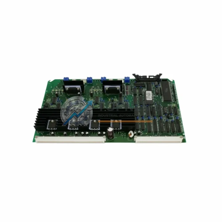
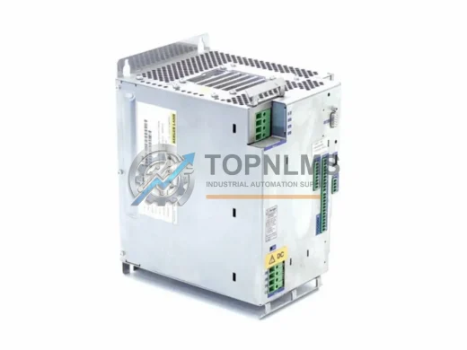
In modern manufacturing and process automation environments, the stepper motor driver is a mission-critical component at the heart of precision motion control. The Stepping 281-500464 Micro Driver Series module is an original industrial spare part engineered for demanding factory floor conditions — delivering reliable pulse-width modulation, stable current output, and consistent micro-stepping performance across a wide range of CNC, packaging, textile, and general-purpose automation systems. Whether you are managing a scheduled maintenance window, responding to an unplanned line stoppage, or building a strategic spare parts inventory, the 281-500464 is a proven, drop-in replacement that restores system stability without requiring firmware reconfiguration or mechanical redesign.
Alternate cross-reference part numbers for this module include 208-500464-2, 281-501049-A, 208-501049-5, and 30-106684A19 — ensuring compatibility across multiple procurement databases, legacy BOM records, and OEM documentation sets. Maintenance engineers and procurement teams can source this part with confidence knowing that all variants are functionally equivalent and interchangeable within the Micro Driver Series platform.
Critical Technical Specs
| Parameter |
Specification |
| Part Number |
281-500464 / 208-500464-2 / 281-501049-A / 208-501049-5 / 30-106684A19 |
| Series |
Micro Driver Series |
| Product Type |
Stepper Motor Driver Module |
| Brand |
Stepping |
| Origin |
China (CN) |
| Drive Technology |
Micro-stepping PWM current control |
| Compatibility |
2-phase and 4-phase stepper motors; drop-in replacement for Micro Driver Series platforms |
| Input Voltage Range |
Refer to OEM datasheet; typical 24–80 VDC for Micro Driver class |
| Output Current |
Configurable via DIP switch; typical 0.5–8.0 A peak per phase |
| Micro-step Resolution |
Up to 1/128 step (model-dependent); selectable via onboard switches |
| Protection Features |
Over-current, over-temperature, short-circuit protection |
| Mounting |
DIN rail or panel mount; standard footprint compatible with Micro Driver Series enclosures |
| Operating Temperature |
0°C to +50°C (ambient); derate above 40°C |
| Communication Interface |
Step/Direction pulse input; optically isolated signal inputs |
| Application Environment |
Industrial automation, CNC machining, packaging lines, textile machinery, conveyor systems |
| Maintenance Recommendation |
Inspect every 12 months or 8,000 operating hours; replace on first sign of thermal stress or erratic motion |
| Warranty |
12 Months — all units tested before shipment |
Preventive Maintenance Strategy
A stepper motor driver failure rarely occurs in isolation. In most industrial control cabinets, the 281-500464 operates as part of an integrated motion control loop that includes upstream power conditioning, signal distribution, and downstream mechanical actuation. When performing a scheduled inspection or emergency replacement of this module, experienced maintenance engineers know that a thorough cabinet audit significantly reduces the risk of repeat failures and secondary downtime events.
Begin by inspecting the 24 VDC or 48 VDC switching power supply that feeds the driver. Voltage ripple or sag under load is a leading cause of stepper driver instability and premature failure — a replacement power supply module should be on hand as a companion spare. Next, check the step/direction signal cable running from the motion controller or PLC output card to the driver’s optically isolated input terminals; damaged shielding or loose ferrule terminations on these cables are a frequent source of missed steps and positioning errors.
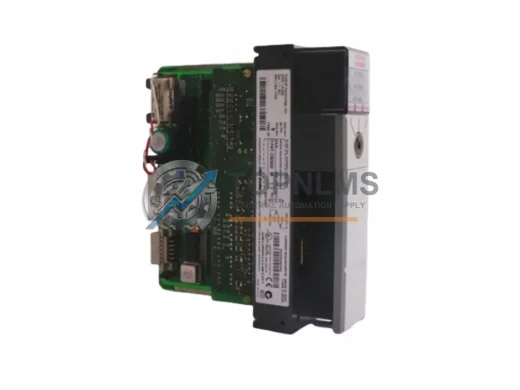
The PLC digital output module generating the pulse train should also be verified — output channel degradation can mimic driver faults and lead to misdiagnosis. If the system uses a motion controller or dedicated CNC interpolator board, confirm that its firmware and parameter tables are backed up before swapping the driver, as some controllers store axis-specific tuning data that must be re-entered after hardware changes.
Inspect the terminal blocks and DIN rail connectors within the control cabinet. Loose or corroded terminals cause intermittent faults that are notoriously difficult to trace during live production. Replacing worn terminal blocks during a planned maintenance window is far less costly than a mid-shift stoppage. Similarly, check the fuse modules and circuit breakers protecting the driver’s power input — a slow-blow fuse that has been thermally stressed over years of operation may not trip at its rated value, allowing damaging overcurrent events to reach the driver.
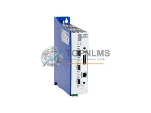
For systems with multiple axes, the I/O expansion modules handling enable signals, fault outputs, and limit switch inputs should be tested for contact integrity. A faulty enable relay or a stuck limit switch input can prevent the driver from energizing even after a successful hardware replacement, leading to unnecessary additional downtime. If the machine uses a fieldbus communication module (such as PROFIBUS-DP, CANopen, or EtherCAT) to coordinate motion commands, verify that the network topology and termination resistors are intact — a degraded bus can cause sporadic axis faults that appear to originate in the driver itself.
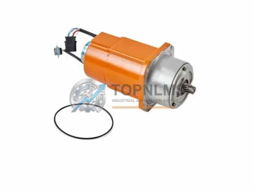
Finally, document the motor winding resistance and insulation resistance of the connected stepper motor. A motor with degraded winding insulation will repeatedly stress replacement drivers, shortening their service life. Keeping a spare stepper motor of the correct frame size and winding specification alongside the 281-500464 driver spare is a best-practice inventory strategy for high-utilization production lines.
Strategic Replacement Solutions
The 281-500464 is designed as a direct replacement for aging Micro Driver Series units that have reached end-of-service-life or have been discontinued by the original equipment manufacturer. Its standardized DIP-switch configuration for current and micro-step selection means that field technicians can restore a failed axis to full operation in under 30 minutes without specialized tools or laptop-based commissioning software — a critical advantage when every minute of downtime carries a measurable production cost.
For facilities managing legacy automation systems built 10–20 years ago, sourcing original spare parts like the 281-500464 is often more cost-effective than a full system retrofit. Retaining the existing mechanical design, wiring harness, and PLC program while replacing only the failed driver module preserves the institutional knowledge embedded in the original system configuration and avoids the risk and expense of a full re-commissioning cycle. The cross-reference part numbers (208-500464-2, 281-501049-A, 208-501049-5, 30-106684A19) ensure that procurement teams can match this part against multiple historical purchase orders and OEM service manuals without ambiguity.
All units supplied by TOPNLMS are sourced from verified industrial channels, individually tested for electrical performance prior to shipment, and backed by a 12-month warranty. Expedited shipping options are available to support emergency maintenance scenarios where production continuity is at risk.
Support FAQ
Q1: Is the 281-500464 compatible with my existing stepper motor and controller?
The 281-500464 is compatible with standard 2-phase and 4-phase stepper motors and accepts universal step/direction pulse inputs from PLCs, motion controllers, and CNC systems. Cross-reference part numbers 208-500464-2, 281-501049-A, 208-501049-5, and 30-106684A19 confirm interchangeability within the Micro Driver Series. If you require compatibility verification for a specific motor or controller model, contact our technical team with your system specifications.
Q2: How is the unit tested before shipment?
Every 281-500464 unit undergoes electrical performance testing prior to dispatch, including power-on verification, output current calibration check, and protection circuit validation. A test report is available upon request. Units are packaged in anti-static protective packaging to prevent ESD damage during transit.
Q3: What is the recommended spare parts inventory strategy for this driver?
For production lines with continuous operation (two or three shifts), we recommend maintaining a minimum of one spare 281-500464 driver per axis group, plus companion spares for the associated power supply module and signal cable assembly. For critical single-axis systems, a 1:1 spare ratio is advisable. Bulk procurement pricing is available for orders of 5 units or more.
Q4: What does the 12-month warranty cover, and what is the replacement process?
The 12-month warranty covers manufacturing defects and electrical failures under normal operating conditions. It does not cover damage resulting from incorrect installation, overvoltage events, or physical impact. To initiate a warranty claim, contact TOPNLMS with your order number and a description of the fault. Replacement units are dispatched within 3–5 business days of claim approval, and defective units must be returned for inspection.