Product Overview
Schneider 140CPS22400 Replacement for Modicon Quantum: Smooth Migration from Legacy Power Infrastructure
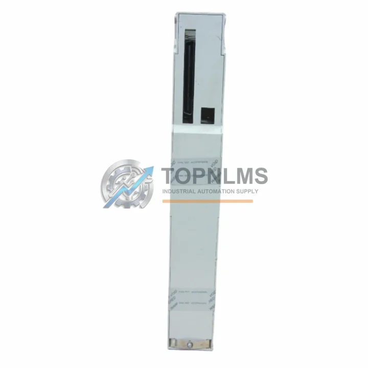
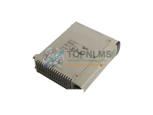
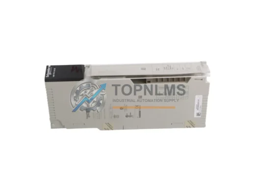
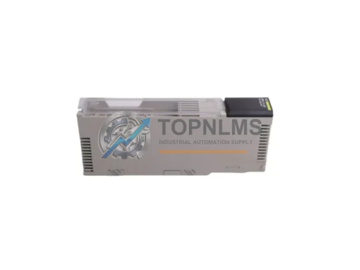
When a Modicon Quantum rack loses its power supply, every minute of unplanned downtime translates directly into production loss. The Schneider Electric 140CPS22400 is a DC 24V, 8A redundant power supply module engineered specifically for the Modicon Quantum automation platform — one of the most widely deployed large-scale PLC architectures in process industries, utilities, and critical infrastructure worldwide. Whether you are replacing a failed unit, building a hot-standby redundancy configuration, or migrating an aging Quantum system to a refreshed hardware baseline, the 140CPS22400 provides a verified drop-in solution that preserves your existing rack geometry, wiring harness, and control program without modification.
Many facilities running Modicon Quantum systems originally commissioned in the 1990s and 2000s are now facing the reality of aging power infrastructure. The 140CPS22400 is the correct replacement for earlier Quantum power supply variants, and it slots directly into the standard Quantum backplane — the 140XBP01600 16-slot rack and the 140XBP00600 6-slot rack — without any mechanical adaptation. The module’s DC 24V input range accommodates the same panel power distribution that feeds your existing Quantum chassis, meaning your upstream 24VDC bus, fusing, and terminal blocks remain unchanged.
For sites operating a redundant Quantum CPU configuration — typically pairing a 140CPU67160 or 140CPU67261 primary controller with a hot-standby counterpart — power supply redundancy is equally critical. The 140CPS22400 supports parallel redundant operation within the same rack, allowing a second unit to assume load instantly upon primary failure. This architecture eliminates the power supply as a single point of failure in safety-critical loops, satisfying the availability requirements of SIL-rated applications and continuous process environments.
Migration projects that involve upgrading from older Quantum CPU modules such as the 140CPU43412A or 140CPU53414B to current-generation processors frequently require a simultaneous audit of the power budget. The 140CPS22400’s 8A output capacity comfortably supports fully populated racks carrying high-density I/O modules — including the 140ACI04000 analog input module, 140DDI35300 discrete input module, and 140DDO35300 discrete output module — without requiring rack segmentation or additional power feed points.
Communication infrastructure within the Quantum platform also depends on stable, clean power. Modules such as the 140NOE77101 Ethernet TCP/IP network option module and the 140NOM21200 Modbus Plus network option module are sensitive to power rail noise and voltage transients. The 140CPS22400’s regulated DC output and built-in filtering ensure that these communication modules maintain link integrity during load transitions, preventing spurious network faults that can trigger unnecessary system shutdowns.
For retrofit projects where the existing Quantum system communicates with field devices over PROFIBUS DP or Modbus RTU, the power supply replacement can be completed without any changes to the communication configuration stored in Unity Pro or Concept programming software. The 140CPS22400 is transparent to the control program — it appears to the CPU and I/O scanner exactly as the original unit, requiring no re-addressing, no re-parameterization, and no modification to the application logic.
Physical installation follows the standard Quantum module insertion procedure: power down the rack, slide the 140CPS22400 into the designated power supply slot, secure the captive screw, reconnect the DC input wiring to the clearly labeled terminal block, and restore power. The module’s front-panel LED indicators provide immediate confirmation of input voltage presence, output regulation status, and redundancy health — allowing field technicians to verify correct installation without connecting a programming terminal.
Procurement teams evaluating the 140CPS22400 as a long-term spares strategy should note that this module is compatible across the full range of Quantum rack sizes and CPU generations, making it an efficient single-SKU solution for multi-site inventory consolidation. Stocking one or two units per facility eliminates the need to maintain separate spare part numbers for different Quantum configurations, reducing carrying costs and simplifying the spare parts management process.
Compatibility Comparison Table
| Parameter |
Legacy / Predecessor Units |
140CPS22400 (This Unit) |
| Input Voltage |
DC 24V (nominal) |
DC 24V (18–30V range) |
| Output Current |
Varies (typically 4A–8A) |
8A continuous |
| Redundancy Support |
Single or optional redundant |
Native parallel redundancy |
| Compatible Racks |
140XBP00600, 140XBP01600 |
140XBP00600, 140XBP01600 (all Quantum racks) |
| Compatible CPUs |
140CPU43412A, 140CPU53414B |
All Quantum CPU generations incl. 140CPU67160, 140CPU67261 |
| Communication Impact |
No change required |
No change required — transparent to CPU and I/O |
| Programming Software |
Concept, Unity Pro |
No re-programming required |
| Installation Method |
Slide-in, captive screw |
Identical — direct drop-in replacement |
| Front Panel Diagnostics |
LED indicators |
LED indicators (input, output, redundancy status) |
| Warranty |
N/A (legacy / end-of-life) |
12-Month Warranty included |
Seamless Upgrade Solutions
A successful Quantum power supply migration rarely involves a single module in isolation. In practice, field engineers replacing the 140CPS22400 are often simultaneously addressing adjacent components that have reached the same service age. The 140XBP01600 backplane itself should be inspected for connector wear and backplane bus integrity — a degraded backplane can cause intermittent faults even with a new power supply installed. Similarly, the 140CRA93100 remote I/O head adapter, commonly used to extend the Quantum system to distributed I/O drops over Modbus Plus, should be verified for firmware currency and connector condition during any planned maintenance window.
On the field wiring side, the 24VDC input terminals of the 140CPS22400 connect to the same panel power distribution as the rest of the control cabinet. If the cabinet also houses a 140CPU67160 CPU module with its associated 140NOM21200 Modbus Plus network card, the power budget calculation should account for the full rack load including all populated I/O slots. For high-density analog applications using the 140ACI04000 or 140ACO02000 analog output module, the 8A output of the 140CPS22400 provides sufficient headroom without requiring a second power feed.
Sites transitioning from legacy Quantum systems to a modernized architecture may also be evaluating the 140NOE77101 Ethernet module as a replacement for older serial communication cards. The 140CPS22400 supports this upgrade path without any power infrastructure changes, as the Ethernet module’s power draw is within the standard Quantum rack budget. Programming cable connectivity — typically via a USB-to-serial adapter targeting the Modbus port on the CPU front panel — is unaffected by the power supply replacement and can be used for online diagnostics immediately after the new module is installed.
Retrofit Guidance FAQ
Q: Do I need to modify my existing wiring when replacing with the 140CPS22400?
No. The 140CPS22400 uses the same DC 24V input terminal block layout as predecessor Quantum power supply modules. Your existing wiring, fusing, and cable routing remain unchanged.
Q: Will my Unity Pro or Concept application program require modification?
No. The power supply module is transparent to the CPU and does not appear as an addressable node in the application program. No re-compilation, re-download, or re-addressing is required.
Q: Can I install the 140CPS22400 in a redundant configuration alongside an existing power supply?
Yes. The 140CPS22400 supports native parallel redundancy within the same Quantum rack. Both units share the load and either can assume full load upon failure of the other, with no interruption to the control program.
Q: Is the 140CPS22400 compatible with all Quantum rack sizes?
Yes. It is compatible with the full range of Quantum backplanes including the 6-slot 140XBP00600 and the 16-slot 140XBP01600, as well as intermediate rack sizes.
Q: What communication protocols are affected by the power supply replacement?
None. Modbus RTU, Modbus Plus, Ethernet TCP/IP, and PROFIBUS DP communication configurations are stored in the CPU and network modules — they are unaffected by the power supply replacement.
Q: How do I verify correct installation without a programming terminal?
The 140CPS22400 front panel provides LED indicators for input voltage presence, output regulation status, and redundancy health. Green LEDs on all three indicators confirm correct installation and normal operation.
Q: What is the physical installation time for a trained technician?
Typically 15–30 minutes including power-down, module swap, wiring reconnection, power restoration, and LED verification. No special tools are required beyond a standard flat-blade screwdriver for the captive screw.
Warranty Assurance
Every 140CPS22400 unit shipped by TOPNLMS is covered by a 12-month warranty from the date of delivery. Prior to shipment, each unit undergoes functional verification including input voltage range testing, output current load testing, and redundancy signaling verification. Units that do not meet Schneider Electric’s original performance specifications are not shipped.
In the event of a warranty claim, TOPNLMS provides direct replacement support with priority processing for critical infrastructure customers. Our technical team is available to assist with installation verification, fault diagnosis, and compatibility confirmation before and after shipment. Replacement units for valid warranty claims are dispatched within 2 business days of claim confirmation.
Stock availability is maintained to support urgent replacement requirements. Orders confirmed before 14:00 CST on business days are processed for same-day dispatch. International shipments are supported with DHL Express, FedEx International Priority, and UPS Worldwide Expedited, with tracking provided at time of dispatch. Export documentation including commercial invoice, packing list, and certificate of origin is prepared for all international orders.
For volume procurement, framework agreements, and multi-site spares programs, please contact our industrial sales team directly to discuss pricing, lead times, and consignment stock arrangements.
© 2026 TOPNLMS. All rights reserved.
Original Source: https://topnlms.com
Contact: [email protected] | +86 18359293191