Product Overview
ODOT CT-121F Replacement/Upgrade Solution for CT Series: Smooth Migration from Legacy Distributed I/O Systems
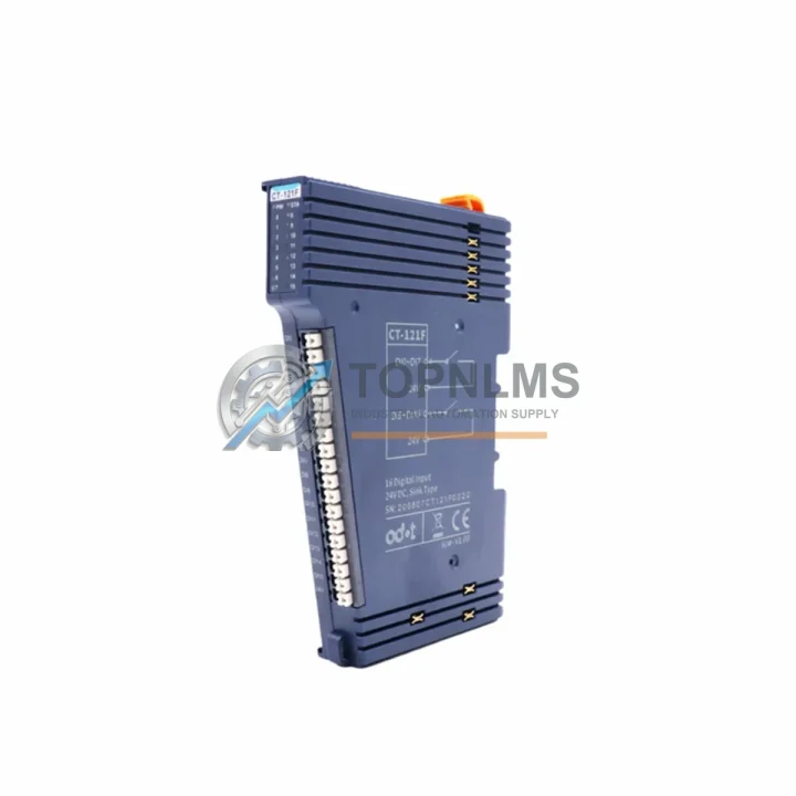
The ODOT CT-121F is a distributed I/O expansion module designed for the ODOT CT Series platform — a widely deployed EtherCAT-based distributed I/O architecture used across manufacturing, process control, water treatment, and building automation applications. As legacy field devices age out and original equipment manufacturers discontinue older I/O node variants, the CT-121F serves as the authoritative replacement and upgrade path for engineers managing brownfield control system modernization projects.
This product page is intended for industrial procurement teams, system integrators, and controls engineers who need a verified, in-stock replacement for discontinued or end-of-life distributed I/O nodes within the ODOT CT Series ecosystem. Whether you are replacing a failed module on an active production line or executing a planned migration from an older distributed I/O architecture, the CT-121F delivers the wiring compatibility, communication protocol alignment, and physical form factor required for a low-disruption installation.
Compatibility Comparison Table
| Parameter |
Legacy / Replaced Model |
ODOT CT-121F (Replacement) |
| Series Platform |
ODOT CT Series (earlier node variants) |
ODOT CT Series — fully compatible |
| Communication Protocol |
EtherCAT (CoE) |
EtherCAT (CoE) — identical protocol stack |
| I/O Expansion Type |
Distributed I/O expansion node |
Distributed I/O expansion module (drop-in) |
| Wiring Interface |
Spring-clamp or screw terminal (CT bus) |
CT bus terminal — same wiring footprint |
| Power Supply Requirement |
24 VDC bus power via CT coupler |
24 VDC via CT coupler — no rewiring required |
| DIN Rail / Rack Mounting |
35 mm DIN rail, side-by-side expansion |
35 mm DIN rail — identical mounting profile |
| Physical Dimensions |
Compact CT module form factor |
Same compact CT module form factor |
| PLC / Controller Compatibility |
EtherCAT master controllers (Beckhoff, Codesys-based, ODOT CN series) |
All EtherCAT master controllers — no program changes required for same I/O mapping |
| ESI / Device Description File |
Legacy ESI file (may require update) |
Updated ESI file available — import into TwinCAT, Codesys, or ODOT Studio |
| Replacement Recommendation |
Direct 1:1 replacement for same-channel-count CT nodes |
Confirmed compatible — verify channel count and I/O type before ordering |
| Warranty |
N/A (legacy / end-of-life) |
12-Month Warranty from TOPNLMS |
Seamless Upgrade Solutions
A successful migration from a legacy distributed I/O system to the ODOT CT-121F rarely involves a single module swap. In practice, controls engineers working on CT Series upgrades will encounter a broader set of component decisions across the control cabinet and field wiring infrastructure.
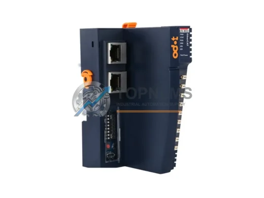
The CT-121F slots into the existing CT bus rail alongside the ODOT CT-100 EtherCAT coupler, which serves as the gateway between the EtherCAT network and the local CT expansion bus. If the coupler itself is aging or has been flagged for replacement during a scheduled maintenance window, it is advisable to source the CT-100 at the same time to avoid a second service call. The coupler manages power distribution to all downstream CT expansion modules, so its health directly affects the reliability of the CT-121F and any adjacent I/O nodes.
For projects where the upstream EtherCAT master is a Codesys-based soft PLC or a dedicated controller such as the ODOT CN-8031 EtherCAT master controller, the CT-121F integrates without requiring changes to the existing PLC program, provided the I/O channel mapping remains consistent. Engineers migrating from a Beckhoff EK1100 coupler and EL series terminals to the ODOT CT platform will find that the EtherCAT process data object (PDO) structure is compatible at the protocol level, though ESI file import into TwinCAT XAE or Codesys IDE is required before the first scan cycle.
In control cabinets where space is constrained, the CT-121F’s compact DIN rail profile allows it to coexist with ODOT CT-141 analog input modules and CT-161 analog output modules without requiring cabinet expansion. This is particularly relevant in retrofit projects where the original cabinet was sized for an older, bulkier I/O system and available rail space is limited. The side-by-side bus connection eliminates inter-module cabling, reducing both installation time and potential wiring fault points.
For applications requiring signal isolation between field instruments and the control bus — common in environments with high electrical noise, variable-frequency drives, or long cable runs — pairing the CT-121F with a dedicated signal isolator or signal conditioner on the input side is recommended. This is especially relevant when migrating from older relay-based I/O panels where galvanic isolation was provided by interposing relays rather than by the I/O module itself.
Communication infrastructure upgrades often accompany I/O node replacements. If the existing EtherCAT network topology uses daisy-chain cabling and the project scope includes adding new nodes, an EtherCAT junction or managed industrial Ethernet switch may be required to support star or tree topologies. The CT-121F supports standard EtherCAT daisy-chain topology natively, so no additional hardware is needed for straightforward node replacements within an existing linear network.
Finally, for commissioning and diagnostics, having an ODOT-compatible USB programming cable or EtherCAT diagnostic tool on-site during the replacement procedure significantly reduces troubleshooting time. The CT-121F can be verified in the EtherCAT network scan before the system is returned to production, confirming correct ESI mapping, PDO assignment, and I/O channel response prior to live operation.
Retrofit Guidance FAQ
Q: Can I replace my existing CT Series I/O node with the CT-121F without rewiring the field terminals?
A: In most cases, yes. The CT-121F uses the same CT bus terminal interface as other CT Series expansion modules. If the channel count and I/O type (digital input, digital output) match your existing node, the field wiring can remain unchanged. Always verify the terminal assignment diagram against your existing wiring documentation before powering up.
Q: Do I need to modify my PLC program after installing the CT-121F?
A: If the CT-121F replaces a module with an identical I/O channel count and type, and the EtherCAT PDO mapping is preserved, no program changes are required. If the ESI file version differs from the one previously imported, re-import the updated ESI file and verify the PDO configuration in your engineering software (TwinCAT, Codesys, or ODOT Studio) before going live.
Q: Is the CT-121F compatible with non-ODOT EtherCAT masters such as Beckhoff or Siemens?
A: The CT-121F communicates via standard EtherCAT (CoE — CANopen over EtherCAT) and is compatible with any EtherCAT master that supports ESI-based device configuration. Beckhoff TwinCAT, Codesys-based controllers, and other standard EtherCAT masters can integrate the CT-121F by importing the provided ESI file. Siemens PROFINET or PROFIBUS systems require an EtherCAT-to-PROFINET gateway and are not directly compatible.
Q: What is the power supply requirement for the CT-121F?
A: The CT-121F is powered via the CT bus from the upstream CT-100 coupler, which accepts 24 VDC input. No separate power wiring to the expansion module is required. Ensure the coupler’s power supply is rated for the total current draw of all connected CT expansion modules.
Q: How much DIN rail space does the CT-121F require?
A: The CT-121F occupies a compact footprint consistent with the CT Series module standard. It mounts on a standard 35 mm DIN rail and connects to adjacent modules via the CT bus connector. No additional spacing is required between modules in normal operating conditions.
Q: What should I check during on-site commissioning after installing the CT-121F?
A: After physical installation, perform an EtherCAT network scan in your engineering software to confirm the CT-121F is detected and its ESI configuration matches the imported device description. Verify PDO mapping, check I/O channel response with a known signal source, and confirm the module status LED indicates normal operation before returning the system to production.
Warranty Assurance
Every ODOT CT-121F unit shipped by TOPNLMS is covered by a 12-month warranty from the date of delivery. Prior to shipment, each unit undergoes functional verification to confirm communication integrity, I/O channel response, and bus interface operation. This pre-shipment testing process is designed to eliminate DOA (dead-on-arrival) failures and reduce the risk of unplanned downtime caused by a defective replacement module arriving on-site.
In the event of a warranty claim, TOPNLMS provides replacement support with priority handling for customers operating in production-critical environments. Our after-sales response team is reachable via email and phone to assess the fault condition, confirm warranty eligibility, and initiate the replacement or repair process. Warranty coverage applies to manufacturing defects and functional failures under normal operating conditions; it does not cover damage resulting from incorrect installation, overvoltage, or environmental conditions outside the module’s rated specifications.
For B2B procurement teams managing spare parts inventory, TOPNLMS maintains stock of the CT-121F to support both immediate replacement orders and planned maintenance purchasing. Lead times, bulk pricing, and consignment stock arrangements are available upon request. Contact our sales team to discuss procurement terms suited to your maintenance schedule and inventory strategy.