Product Overview
Mitsubishi Electric S-N65 Replacement/Upgrade Solution for S-N Series: Seamless Transition from Legacy Motor Control Systems
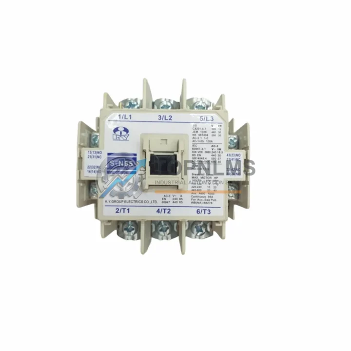
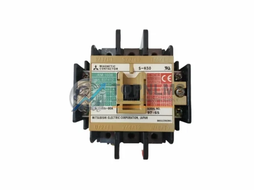
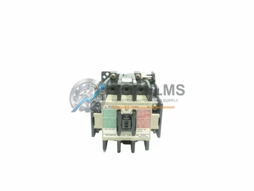
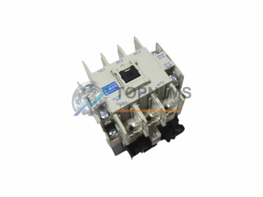
When your existing motor control panel relies on the Mitsubishi Electric S-N65 65A magnetic contactor — or an older discontinued model from the S-N Series such as the S-N50 or S-N80 — sourcing a verified, drop-in compatible replacement is critical to minimizing production downtime. The S-N65 is a 3-pole AC magnetic contactor rated at 65A, designed for AC motor starter applications across a wide range of industrial environments including manufacturing lines, HVAC systems, pump control panels, compressor stations, and conveyor drive systems.
This listing provides a genuine Mitsubishi Electric S-N65 unit suitable for direct replacement of end-of-life or failed contactors within existing S-N Series motor control centers (MCCs), control cabinets, and distribution panels. Whether you are executing a planned maintenance swap, an emergency field replacement, or a phased modernization of legacy motor starters, the S-N65 delivers full backward compatibility with the original wiring layout, coil voltage options, and DIN rail or panel-mount footprint.
Compatibility Comparison Table
| Parameter |
Legacy / Outgoing Model |
S-N65 (This Unit) |
Replacement Notes |
| Rated Current |
S-N50 (50A) / S-N80 (80A) |
65A |
Verify motor FLA; S-N65 covers most 30–45kW loads at 400V |
| Pole Configuration |
3-pole (standard) |
3-pole |
Direct replacement; no rewiring of main power terminals |
| Coil Voltage |
AC 110V / 220V / 380V options |
AC 100–240V (specify on order) |
Confirm control circuit voltage before ordering |
| Auxiliary Contacts |
1NO+1NC (standard) |
1NO+1NC (built-in) |
Compatible with existing PLC digital input wiring |
| Mounting Style |
DIN rail / panel screw |
DIN rail / panel screw |
No cabinet modification required |
| Terminal Compatibility |
Screw-type, standard pitch |
Screw-type, standard pitch |
Existing cable lugs and ferrules reusable |
| Communication Interface |
Hardwired (no fieldbus) |
Hardwired (no fieldbus) |
Compatible with relay output modules on Mitsubishi MELSEC Q/L/iQ-R PLCs |
| Overload Relay Pairing |
TH-N Series thermal overload |
TH-N65 / TH-N65KP |
Snap-on mounting; no additional bracket needed |
| Enclosure Fit |
Standard MCC / control cabinet |
Same footprint as S-N50/S-N80 |
No panel cutout modification required |
| Warranty |
— |
12-Month Warranty |
Covered from date of shipment; replacement or refund |
Seamless Upgrade Solutions
A successful migration from a legacy motor control system to a modernized architecture built around the S-N65 typically involves more than a single contactor swap. In practice, field engineers and procurement teams sourcing the S-N65 are often simultaneously addressing adjacent components within the same control cabinet or motor control center.
For systems where the S-N65 is controlled by a Mitsubishi MELSEC iQ-R Series PLC — such as the R04CPU or R08CPU — the contactor’s coil is typically driven through a relay output module like the RY40PT5B or a transistor output module with an interposing relay. If the existing program logic was written for an older Q Series CPU (Q06UDEHCPU or Q13UDHCPU), the ladder rungs controlling the contactor output coil can generally be migrated without structural changes, since the output addressing convention is preserved across MELSEC generations.
In many retrofit projects, the S-N65 is installed alongside a TH-N65 thermal overload relay, which snaps directly onto the contactor body without additional hardware. This pairing is the standard motor starter combination for loads in the 30–45kW range at 380–400V AC. Where the original installation used a separate bimetallic overload relay mounted on a DIN rail, the integrated snap-on design of the TH-N Series significantly reduces panel wiring complexity and cabinet space consumption.
For systems that include a CC-Link or CC-Link IE Field network — common in Mitsubishi-centric automation architectures — the contactor’s status feedback (auxiliary contact signal) is typically wired back to a remote I/O station such as the AJ65SBTB1-16D input module or, in newer installations, an NZ2GF2B1-16D CC-Link IE Field Basic remote I/O unit. These modules relay the contactor’s ON/OFF status to the PLC CPU for interlocking, alarm, and energy monitoring logic.
Where the motor drive system has been upgraded to a Mitsubishi FR-A800 Series inverter drive, the S-N65 is often retained as the main circuit isolation contactor upstream of the drive input, or as a bypass contactor in variable frequency drive (VFD) bypass circuits. In this configuration, the contactor must be rated for AC-3 duty at the full motor current, which the S-N65 satisfies for motors up to approximately 37kW at 400V.
Control cabinet power distribution in these systems typically relies on a CP30 Series circuit protector or an NF Series molded case circuit breaker (MCCB) as the upstream protective device for the contactor feeder circuit. Ensuring the upstream MCCB’s breaking capacity and trip curve are coordinated with the S-N65’s inrush current characteristics is a standard step in the retrofit commissioning checklist.
For facilities managing a broader MELSEC-based control architecture, the S-N65 replacement project is often bundled with a review of the GOT2000 Series HMI (such as the GT2710-VTBA) to update motor status display screens, alarm setpoints, and maintenance hour counters that reference the contactor’s operational cycle count.
Retrofit Guidance FAQ
Q: Can I reuse the existing control wiring when replacing an S-N50 or S-N80 with the S-N65?
A: Yes. The S-N Series uses a consistent terminal layout across the 50A–80A frame size range. The main power terminals (L1/L2/L3 and T1/T2/T3) and auxiliary contact terminals (NO/NC) maintain the same physical position and screw pitch. Existing cable lugs, ferrules, and duct wiring can be reused without modification in the vast majority of installations.
Q: Is the S-N65 compatible with Mitsubishi MELSEC PLC relay output modules?
A: Yes. The S-N65 coil draws standard AC control current well within the switching capacity of Mitsubishi relay output modules (RY series) and is also compatible with interposing relay arrangements used with transistor output modules. No changes to the PLC output module or program are required when replacing a same-series contactor.
Q: What communication protocols does the S-N65 support?
A: The S-N65 is a hardwired contactor and does not natively support fieldbus protocols such as CC-Link, PROFIBUS, or EtherNet/IP. Control and status feedback are handled via hardwired coil voltage and auxiliary contact signals. Integration with CC-Link or CC-Link IE Field networks is achieved through remote I/O modules connected to the auxiliary contacts, which is the standard architecture in Mitsubishi MELSEC systems.
Q: Will the S-N65 fit in the same panel space as the unit being replaced?
A: The S-N65 shares the same DIN rail footprint and panel-mount hole pattern as other S-N Series contactors in the 50A–80A range. No cabinet modification, new DIN rail section, or panel cutout rework is required for a direct swap. The overall height, width, and depth are within the same envelope, ensuring compatibility with existing cable management ducts and adjacent component clearances.
Q: Can the S-N65 be used in a star-delta (Y-Δ) motor starter configuration?
A: Yes. The S-N65 is suitable for use as the main contactor, star contactor, or delta contactor in a star-delta starter assembly, provided the current ratings are correctly matched to the motor’s full-load current. Mechanical and electrical interlocking between contactors in a star-delta configuration follows standard Mitsubishi S-N Series wiring practice.
Q: What is the lead time and shipping arrangement?
A: Units are stocked in Xiamen and are typically dispatched within 1–3 business days of order confirmation. International shipments are handled via DHL Express, FedEx, or UPS depending on destination. Domestic China orders are shipped via SF Express or JD Logistics. All units are tested prior to dispatch and shipped with original packaging.
Warranty Assurance
Every S-N65 unit supplied by TOPNLMS is covered by a 12-month warranty from the date of shipment. This warranty covers manufacturing defects, coil failure, contact welding under normal operating conditions, and mechanical actuation faults. It does not cover damage resulting from incorrect installation, overvoltage, short-circuit events beyond the rated breaking capacity, or unauthorized disassembly.
Prior to dispatch, each unit undergoes a pre-shipment inspection that includes coil continuity verification, auxiliary contact function test, and visual inspection of the contact assembly and terminal block. Units that do not pass inspection are quarantined and not shipped.
In the event of a warranty claim, TOPNLMS will arrange for a replacement unit to be dispatched upon receipt and verification of the defective item, or issue a full refund at the buyer’s discretion. Warranty claims are processed within 5 business days of receiving the returned unit. After-sales support is available via email and phone during business hours (GMT+8), and technical assistance for installation and commissioning questions is provided at no additional charge.
For procurement teams managing planned maintenance schedules, TOPNLMS can provide batch quotations, reserved stock arrangements, and documentation packages including test reports and certificates of conformity upon request.