
KONTRON
KONTRON CP6000 Replacement/Upgrade for CompactPCI Serial
CP6000KONTRON CP6000 CompactPCI Serial CPU module replacement & upgrade solution. Compatible with legacy cPCI Serial systems. 12-month warranty. Fast global shipping.
Request availability, condition, lead time and export shipping details for VC1A-REG97.
Send this exact part number, quantity and destination country. TOPNLMS will confirm availability, condition and export lead time before quotation.
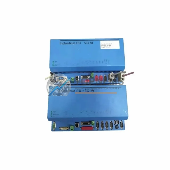
The Kontron VC1A-REG97 is a VME-bus Register Control Module designed for high-reliability industrial control environments. As legacy VME-based control systems approach end-of-life or face discontinued spare-parts availability, facilities running Kontron VC1A-series backplanes, VME64 crates, and associated I/O infrastructure are increasingly seeking verified drop-in replacements that preserve existing wiring, rack geometry, and software logic without forcing a full platform migration.
TOPNLMS supplies the VC1A-REG97 as a tested, ready-to-ship replacement module for customers migrating away from obsolete or hard-to-source VME register controllers. Whether your plant is running a legacy Kontron CPCI/VME hybrid rack, a standalone VME64x crate, or an embedded control cabinet built around the VC1A platform, this module is engineered to slot in with minimal re-engineering effort.
| Parameter | Legacy / Outgoing Module | VC1A-REG97 (Replacement) |
|---|---|---|
| Model / SKU | Kontron VC1A-REG (earlier revisions), third-party VME register cards | Kontron VC1A-REG97 |
| Bus Standard | VME / VME64 | VME / VME64 (backward compatible) |
| Form Factor | 6U VME single-slot | 6U VME single-slot |
| Connector Interface | P1 / P2 DIN 41612 | P1 / P2 DIN 41612 (pin-compatible) |
| Power Supply | +5 V / ±12 V from VME backplane | +5 V / ±12 V from VME backplane |
| Communication Protocol | VMEbus (ANSI/IEEE 1014) | VMEbus (ANSI/IEEE 1014) |
| Register / I/O Mapping | Hardware address-switch configurable | Hardware address-switch configurable (same scheme) |
| Installation Space | Standard VME slot in 19″ rack crate | Standard VME slot in 19″ rack crate (no mechanical modification) |
| Software / Driver Compatibility | VxWorks, LynxOS, RTEMS, custom RTOS | Compatible with existing VME driver stacks; no firmware rewrite required |
| Replacement Recommendation | Direct drop-in for same-series VC1A register modules | ✔ Confirmed drop-in replacement |
| Warranty | OEM warranty expired / discontinued | 12-Month Warranty from TOPNLMS |
A successful VC1A-REG97 retrofit rarely involves a single module swap. In practice, engineers migrating from aging VME-based control systems will encounter a chain of interdependent components that must be evaluated in parallel. The following describes the typical upgrade pathway and the associated components commonly addressed during the same maintenance window.
The Kontron MPCX-series VME CPU board is frequently the host processor driving the VC1A register module. When the REG97 is replaced, the CPU board’s address map and interrupt vector assignments should be verified to confirm compatibility with the new module revision. In systems where the CPU board itself is approaching obsolescence, customers often source a replacement CPU card alongside the REG97 to complete the rack refresh in a single planned outage.
The VME64x backplane — typically a 6- or 9-slot passive backplane — is the physical and electrical backbone connecting the VC1A-REG97 to the rest of the control system. Inspecting the backplane for oxidized P1/P2 connector pins and verifying slot termination resistors is a standard pre-installation step. Customers running older 21-slot VME crates sometimes take the opportunity to migrate to a more compact 6U VME chassis during the same retrofit, reducing cabinet footprint.
Power integrity is critical in VME environments. The VME system power supply module — responsible for delivering stable +5 V and ±12 V rails to the backplane — should be load-tested before the new REG97 is commissioned. Aging linear or switching power supplies in legacy VME crates are a common source of intermittent register read/write errors that are often misdiagnosed as module faults. Replacing the power supply alongside the VC1A-REG97 eliminates this variable from the commissioning process.
For systems that rely on VME-to-serial or VME-to-fieldbus transition modules — such as VME PROFIBUS-DP interface cards or VME CANbus adapters — the register address space used by the VC1A-REG97 must be confirmed not to conflict with the address ranges assigned to these communication modules. In multi-master VME architectures, this is particularly important when the REG97 is used as a shared-memory or mailbox register between the CPU and a co-processor card.
Wiring to the front-panel I/O of the VC1A-REG97 is typically routed through DIN rail terminal blocks or a signal conditioning / isolation module mounted in the same control cabinet. During replacement, it is good practice to inspect the field wiring terminations, verify signal levels against the module’s input specifications, and replace any degraded terminal blocks. Customers running 24 VDC discrete I/O signals through opto-isolated input modules adjacent to the VME crate should confirm that the isolation barrier ratings remain within specification after the module swap.
In facilities where the VME control system interfaces with a SCADA or DCS layer via an OPC-DA or OPC-UA gateway, the data point mapping for the register module’s I/O channels should be re-validated after installation. The OPC server configuration — whether running on a dedicated industrial PC or embedded in a Kontron CompactPCI SBC — will need to confirm that the register offsets and data types assigned to the VC1A-REG97 channels match the new module’s hardware revision documentation.
Finally, customers who maintain a VME programming and diagnostic cable (typically a USB-to-VME or Ethernet-to-VME interface adapter) for in-situ register read/write testing will find this tool indispensable during the commissioning phase. Running a register loopback test immediately after installation — before reconnecting field wiring — is the fastest way to confirm that the VC1A-REG97 is correctly addressed and responding on the VMEbus.
Q: Can I replace the VC1A-REG97 without modifying my existing field wiring?
A: Yes. The VC1A-REG97 uses the same P1/P2 DIN 41612 connector pinout as earlier VC1A register module revisions. Field wiring connected to the front-panel terminal interface does not need to be re-terminated, provided the wiring was originally installed to the VC1A specification.
Q: Do I need to update my VME driver or RTOS software after installing the REG97?
A: In most cases, no. The VC1A-REG97 maintains register-level compatibility with earlier VC1A revisions. Existing VME driver code targeting the same base address and register map will continue to function. However, if your system uses a hardware revision check at startup, you may need to update the revision constant in your initialization routine.
Q: Is the VC1A-REG97 compatible with VME64 and VME64x backplanes?
A: The module is designed for standard VME (ANSI/IEEE 1014) and VME64 environments. Compatibility with VME64x extended backplanes (which add the P0 connector row) depends on whether your system uses the P0 connector for power or user-defined I/O. Confirm your backplane’s P0 usage before installation.
Q: What communication protocols does the VC1A-REG97 support?
A: The module communicates exclusively over the VMEbus (ANSI/IEEE 1014) parallel backplane protocol. It does not natively support Ethernet, PROFIBUS, or other fieldbus protocols. Integration with higher-level networks is handled by separate VME communication interface cards installed in adjacent slots.
Q: Will the module fit in my existing 19″ VME rack without mechanical modification?
A: Yes. The VC1A-REG97 is a standard 6U single-slot VME module and fits any 19″ VME crate with a compatible 6U slot. No bracket modification or panel cutout is required.
Q: How do I verify the module is functioning correctly after installation?
A: Use a VME diagnostic utility (via USB-to-VME or Ethernet-to-VME adapter) to perform a register read/write loopback test at the module’s configured base address before reconnecting field wiring. This confirms correct bus arbitration, address decoding, and data path integrity.
Every Kontron VC1A-REG97 module shipped by TOPNLMS is covered by a 12-month warranty from the date of delivery. Prior to shipment, each unit undergoes a functional verification procedure that includes VMEbus communication testing, register read/write validation, and visual inspection for connector pin condition and PCB integrity.
If a module is found to be defective within the warranty period, TOPNLMS will arrange a replacement shipment or issue a refund, subject to return inspection. Our technical team is available to assist with installation questions, compatibility verification, and commissioning support via email and phone.
We maintain stock of the VC1A-REG97 and related VME-series components to support urgent replacement requirements. Express shipping from our Xiamen warehouse is available for time-critical plant maintenance scenarios. Lead times and shipping options are confirmed at the time of order.
For procurement inquiries, compatibility questions, or bulk order pricing, contact our industrial automation parts team directly.
KONTRON CP6000 CompactPCI Serial CPU module replacement & upgrade solution. Compatible with legacy cPCI Serial systems. 12-month warranty. Fast global shipping.
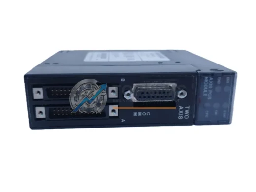
IC693APU302 single-axis APU replacement for GE Fanuc Series 90-30 PLC. Drop-in compatibility, 12-month warranty, fast global shipping from Xiamen.
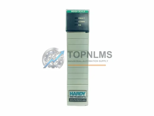
HARDY 1756-2WS dual-channel weigh scale module for ControlLogix. Rugged, EMI-resistant, 12-month warranty. In stock — fast global shipping from TOPNLMS.
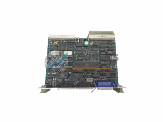
Drop-in replacement for FUJI ELECTRIC Z-312J PLC CPU Module. Z-Series compatible, wiring & protocol ready. 12-month warranty. Ships from Xiamen.
Click Quote This Model and the Part Number field will auto-fill with VC1A-REG97.