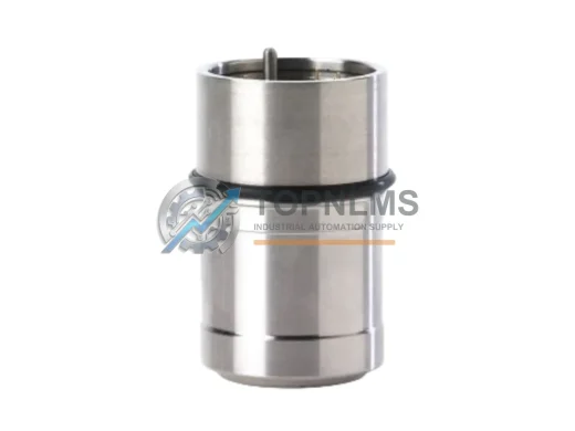
Product Overview
Honeywell C7061A1012 Original Industrial Spare C7061 Compatible: System Stability & Industrial Spare Parts Maintenance Value
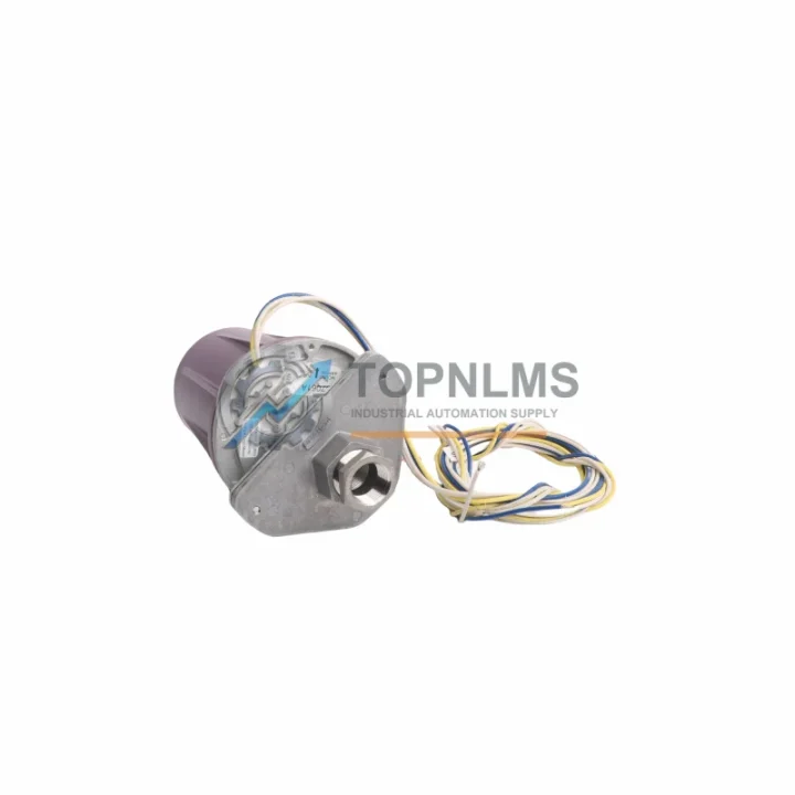
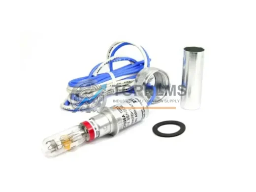
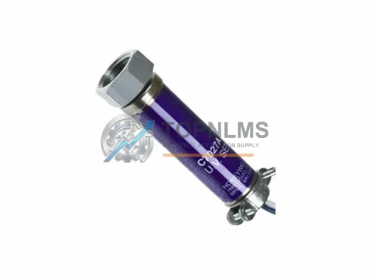
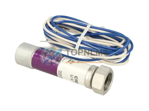
The Honeywell C7061A1012 is a factory-original UV flame detector engineered for continuous duty in industrial combustion control and burner management systems. As a direct replacement spare within the C7061 Series, this detector is designed to restore full system integrity with zero compromise on safety performance. For maintenance engineers managing boiler rooms, process heaters, industrial furnaces, and thermal oxidizers, having a verified C7061A1012 in stock is not optional — it is a fundamental pillar of a sound preventive maintenance strategy.
Unplanned burner shutdowns caused by a failed flame detector can cascade into costly production halts, emergency service calls, and regulatory compliance exposure. The C7061A1012 eliminates that risk by providing a proven, drop-in replacement that restores the original UV sensing sensitivity and relay output behavior of the C7061 Series without requiring reconfiguration of the burner management controller. Whether you are managing a single industrial boiler or a multi-burner process line, maintaining at least one C7061A1012 as a shelf spare is the most cost-effective insurance against unplanned downtime.
Critical Technical Specs Table
| Part Number |
C7061A1012 |
| Series |
C7061 |
| Manufacturer |
Honeywell |
| Product Type |
UV Flame Detector |
| Detection Method |
Ultraviolet (UV) Radiation Sensing |
| Supply Voltage |
24 VDC / 120 VAC / 240 VAC (model-dependent) |
| Output |
Relay contact output for flame signal to burner management system |
| Response Time |
≤ 1 second flame detection; ≤ 3 seconds flame loss |
| Operating Temperature |
-40°C to +70°C ambient |
| Ingress Protection |
IP65 (dust-tight, jet-water resistant) |
| Mounting |
Standard 1-inch NPT threaded sight pipe or direct flange mount |
| Compatibility |
Honeywell R4343, R7847, R7848, R7849 flame amplifiers; RM7800 series burner controls |
| Application Environment |
Industrial boilers, process heaters, thermal oxidizers, industrial furnaces, gas turbines |
| Certifications |
UL Listed, CE Marked, FM Approved |
| Origin |
United States |
| Warranty |
12 Months — Tested before shipment, full replacement guarantee |
Preventive Maintenance Strategy
A UV flame detector like the C7061A1012 does not operate in isolation. It is one node in a tightly integrated combustion safety chain, and its reliability depends on the health of every adjacent component. When scheduling a planned maintenance window or responding to a nuisance shutdown, experienced maintenance teams use the opportunity to inspect and, where necessary, replace the surrounding components that share the same duty cycle and failure modes.
Begin with the flame amplifier module — the C7061A1012 pairs directly with Honeywell R7847, R7848, or R7849 amplifiers. A degraded amplifier can cause intermittent flame signal loss even when the detector itself is functioning correctly. Inspect the amplifier’s sensitivity setting and check for relay contact wear. If the amplifier is more than five years old and the detector is being replaced, replacing both simultaneously eliminates the most common source of recurring nuisance trips.
Next, inspect the burner management relay module — typically a Honeywell RM7800 series or equivalent — which interprets the flame signal and controls the fuel valve sequence. Relay contacts in the RM7800 are subject to arcing wear over thousands of ignition cycles. A worn relay module can misinterpret a valid flame signal as a loss event, triggering unnecessary lockouts. Pairing a new C7061A1012 with a verified RM7800 module ensures the entire detection-to-control chain is operating within specification.
The UV sight pipe and viewing window are frequently overlooked during flame detector replacement. Soot accumulation, condensation, or cracked quartz glass in the sight pipe will attenuate the UV signal reaching the detector, causing false loss-of-flame trips even with a brand-new C7061A1012 installed. Clean or replace the sight pipe assembly as part of every detector swap.
For the electrical circuit, inspect the terminal block and wiring harness connecting the detector to the amplifier and control panel. Loose terminals, corroded contacts, or undersized conductors introduce resistance that can corrupt the low-level flame signal. Replace any suspect terminal blocks and verify conductor insulation integrity with a megohmmeter before commissioning the new detector.
If the burner system includes a pilot gas solenoid valve or main fuel shutoff valve, verify their response times and leak-tightness during the same maintenance window. A slow-opening solenoid can delay pilot flame establishment, causing the C7061A1012 to report a flame failure during the trial-for-ignition period. Solenoid valve coils and seat seals are consumable items that should be on the same replacement schedule as the flame detector.
Finally, review the ignition transformer and spark electrode condition. A weak ignition spark reduces the probability of reliable pilot flame establishment, which in turn increases the number of ignition attempts and the thermal stress on the C7061A1012’s UV tube. Replacing the ignition transformer and electrode gap-setting at the same time as the flame detector is a best-practice that significantly extends the service life of the new detector.
For facilities running Honeywell-based distributed control or safety instrumented systems, also consider the status of associated I/O modules, signal isolators, and communication modules that carry the flame status signal upstream to the DCS or SIS. A degraded signal isolator between the burner panel and the control room can introduce noise that masks a valid flame signal at the supervisory level, even when the C7061A1012 and its local amplifier are performing correctly.
Strategic Replacement Solutions
The C7061A1012 is a direct, form-fit-function replacement for earlier C7061 Series variants including the C7061A1004 and C7061A1020. No wiring changes, no amplifier reconfiguration, and no software parameter updates are required when substituting the C7061A1012 for these legacy part numbers. This backward compatibility is critical for facilities operating aging combustion systems where the original OEM documentation may be incomplete or unavailable.
For sites that have been sourcing aftermarket or grey-market UV detectors as a cost-reduction measure, the C7061A1012 from TOPNLMS represents a return to factory-original performance standards. Aftermarket detectors frequently exhibit reduced UV sensitivity, shorter UV tube service life, and non-compliant relay timing that can cause safety system audit failures. Switching back to a genuine Honeywell C7061A1012 eliminates these compliance risks and restores the system to its original certified configuration.
Procurement teams managing multi-site operations should consider establishing a minimum stock level of two units per burner train for the C7061A1012. With a typical field service life of three to five years under continuous duty, a two-unit buffer provides coverage for one emergency replacement plus one planned maintenance swap without triggering an emergency purchase order. This inventory posture reduces mean time to repair (MTTR) for flame detector failures from days to hours.
All C7061A1012 units supplied by TOPNLMS are sourced from authorized distribution channels, individually tested for UV sensitivity and relay output timing prior to shipment, and covered by a 12-month replacement warranty. Units are shipped in original Honeywell packaging with full traceability documentation, supporting your site’s spare parts audit and quality management requirements.
Support FAQ
Q1: What is the expected service life of the C7061A1012 in continuous industrial duty?
Under normal operating conditions — clean sight pipe, ambient temperature within specification, and ignition cycle frequency within design limits — the C7061A1012 UV tube has a rated service life of approximately 10,000 hours of UV exposure. For boilers operating 24/7, this translates to a planned replacement interval of 12 to 18 months. Facilities with seasonal or intermittent burner operation may achieve three to five years between replacements. TOPNLMS recommends establishing a calendar-based replacement schedule rather than waiting for failure.
Q2: How do I verify compatibility between the C7061A1012 and my existing flame amplifier before installation?
The C7061A1012 is compatible with Honeywell R7847, R7848, and R7849 amplifier modules, as well as the older Q7800 series amplifier bases used with RM7800 burner controls. Check the amplifier model number on the existing unit’s label. If your amplifier is not in this list, contact TOPNLMS at [email protected] with your full system model numbers for a compatibility confirmation before ordering.
Q3: What pre-shipment testing is performed on each C7061A1012 unit?
Every C7061A1012 unit supplied by TOPNLMS undergoes individual functional testing including UV sensitivity verification, relay output timing measurement, and insulation resistance check before packaging. A test record is included with each shipment. Units that do not meet Honeywell’s published specification are quarantined and not shipped. This testing protocol is the basis for our 12-month replacement warranty.
Q4: What is the warranty and return process if a unit fails in the field within the warranty period?
TOPNLMS provides a 12-month replacement warranty from the date of shipment. If a C7061A1012 fails in normal service within this period, contact [email protected] with your order number, installation date, and a brief description of the failure mode. We will arrange a replacement shipment within 3 business days. Failed units should be returned in original packaging for failure analysis. Warranty does not cover damage caused by incorrect installation, overvoltage, or contamination of the UV sight path.