
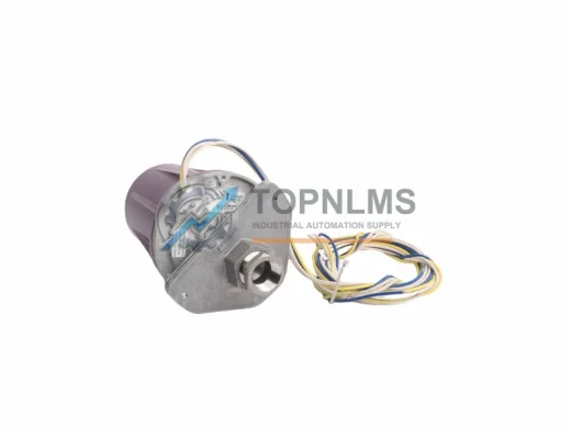
Honeywell
Honeywell C7061A1012 Original Industrial Spare C7061 Compatible
C7061A1012Honeywell C7061A1012 original UV flame detector, C7061 Series. Industrial burner safety replacement. Fast shipping, 12-month warranty. topnlms.com
Request availability, condition, lead time and export shipping details for C7035A1023 C7035A1064.
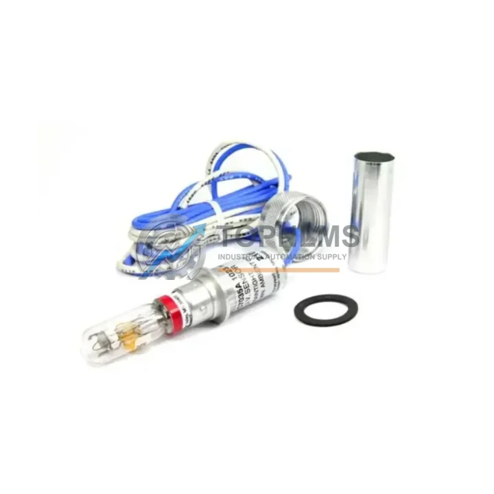
Send this exact part number, quantity and destination country. TOPNLMS will confirm availability, condition and export lead time before quotation.
In industrial combustion control systems, the UV flame sensor is one of the most safety-critical components in the entire burner management loop. The Honeywell C7035A1023 and C7035A1064 are original UV flame detectors from the C7035 Series, engineered for reliable flame presence detection in industrial burners, boilers, process heaters, and thermal oxidizers. When this sensor degrades or fails, the entire burner safety interlock chain is compromised — leading to unplanned shutdowns, failed ignition sequences, and potential safety incidents. Maintaining a verified original spare on the shelf is not optional for facilities running continuous combustion processes.
The C7035 Series sensors are designed to interface directly with Honeywell’s R7847, R7848, and R7849 flame amplifiers, as well as the RM7800 Series burner management relay modules. This tight integration means that substituting with non-original or incompatible sensors can introduce signal timing mismatches, false-flame or no-flame fault codes, and amplifier lockout conditions. Sourcing the original C7035A1023 or C7035A1064 ensures that the sensor-amplifier pairing remains within factory-specified detection thresholds and response times.
| Parameter | Specification |
|---|---|
| Model Numbers | C7035A1023 / C7035A1064 |
| Series | Honeywell C7035 |
| Sensor Type | UV (Ultraviolet) Flame Detector |
| Spectral Response | 185–260 nm (UV range) |
| Supply Voltage | 120 VAC / 240 VAC (model-dependent) |
| Output Signal | Flame relay signal to compatible amplifier |
| Compatible Amplifiers | R7847A, R7848A, R7849A |
| Compatible BMS Modules | RM7800L, RM7800G, RM7840L |
| Operating Temperature | -40°C to +70°C |
| Mounting | 1/2″ NPT threaded sight pipe |
| Ingress Protection | IP40 (standard enclosure) |
| Country of Origin | Germany |
| Application | Industrial burners, boilers, process heaters, thermal oxidizers |
| Warranty | 12 Months from date of shipment |
A UV flame sensor does not fail in isolation. In most industrial combustion systems, the C7035A1023 or C7035A1064 operates as part of a tightly coupled safety chain. During scheduled burner maintenance or annual boiler inspection, maintenance engineers should treat the flame sensor replacement as a trigger point for a broader system audit.
Begin with the flame amplifier — the R7847A or R7848A amplifier module that processes the C7035’s UV signal should be inspected for relay contact wear, terminal corrosion, and sensitivity drift. Amplifiers operating beyond five years in high-cycle environments are prime candidates for proactive replacement alongside the sensor. Next, inspect the RM7800 Series burner management relay module: check the program card, verify lockout history via the diagnostic port, and confirm that the safety timing sequences remain within specification.
The ignition transformer and ignition electrodes should also be checked during the same maintenance window. A degraded ignition spark reduces the UV signal intensity during the trial-for-ignition period, which can cause the C7035 to report a weak-flame or no-flame condition even when combustion is occurring. Pairing a new C7035A1023 with worn ignition components defeats the purpose of the sensor replacement.
Wiring integrity between the sensor, amplifier, and BMS module is another common failure point. Inspect the shielded signal cable runs for insulation cracking, connector oxidation, and ground continuity. In high-temperature environments near the burner, cable management clips and conduit seals should be replaced on the same cycle as the sensor. The sight pipe alignment should also be verified — a misaligned or soot-fouled sight pipe will attenuate the UV signal and cause nuisance lockouts even with a new sensor installed.
For facilities running Honeywell’s DCS or safety PLC infrastructure, the flame signal input card — typically an analog or digital I/O module in the S9000 or HC900 controller family — should be tested for input impedance and signal threshold calibration. A drifted input card can misinterpret a healthy C7035 signal as a fault condition. Similarly, the terminal blocks and DIN rail-mounted relay modules in the burner control cabinet should be inspected for loose terminations and contact resistance, as these introduce voltage drops that affect sensor signal integrity.
Finally, review the combustion air proving switch and gas pressure switches in the same maintenance cycle. These interlock devices work in sequence with the flame sensor during the pre-purge and ignition phases. A sticky or out-of-calibration pressure switch can mask a genuine flame sensor issue or create intermittent lockout patterns that are difficult to diagnose without replacing all suspect components simultaneously.
The C7035A1023 and C7035A1064 are direct replacements for aging UV flame sensors in legacy Honeywell burner management systems. Many industrial facilities continue to operate RM7800-based combustion control systems that were installed in the 1990s and 2000s. These systems remain mechanically sound and control-logic stable, but the consumable sensing components — particularly the UV tube within the C7035 — have finite service lives typically rated at 10,000 to 20,000 operating hours.
Rather than replacing the entire burner management system, facilities can extend the operational life of their existing Honeywell infrastructure by maintaining a stock of original C7035 Series sensors. This approach preserves the validated safety logic, avoids costly re-commissioning and safety integrity level (SIL) re-certification, and keeps maintenance procedures familiar to existing plant personnel.
For facilities managing multiple burner trains, a recommended strategy is to maintain a minimum of two C7035A1023 or C7035A1064 units per burner management panel as on-site spares. This ensures that a sensor failure during a production run can be resolved within a single shift without waiting for emergency procurement. The original Honeywell part also ensures that the UV spectral response characteristics remain consistent with the amplifier’s factory calibration, avoiding the sensitivity recalibration that is often required when using aftermarket alternatives.
When replacing the C7035 in the field, always perform a full burner management system functional test after installation: verify the pre-purge timing, trial-for-ignition sequence, flame signal strength reading at the amplifier, and lockout response to a simulated flame failure. Document the replacement in the equipment maintenance log and update the spare parts inventory accordingly.
Q1: What is the service life of the Honeywell C7035A1023 / C7035A1064, and when should I plan replacement?
The UV sensing element in the C7035 Series has a rated service life of approximately 10,000–20,000 operating hours depending on duty cycle and ambient conditions. For continuous-operation burners, this typically corresponds to 2–4 years of service. Proactive replacement at the 3-year mark during scheduled maintenance shutdowns is recommended to avoid unplanned failures.
Q2: How do I verify compatibility between the C7035A1023 / C7035A1064 and my existing flame amplifier?
The C7035A1023 and C7035A1064 are compatible with Honeywell R7847A, R7848A, and R7849A flame amplifiers, as well as RM7800 Series burner management modules. Verify the amplifier model number on the existing unit and cross-reference with Honeywell’s C7035 Series product bulletin. If the amplifier model is outside this range, contact our technical team before ordering.
Q3: What pre-shipment testing is performed, and what does the 12-month warranty cover?
Every C7035A1023 and C7035A1064 unit is inspected and function-tested prior to shipment. The 12-month warranty covers manufacturing defects and component failures under normal operating conditions. It does not cover damage resulting from incorrect installation, voltage surges, or operation outside the specified environmental range. Warranty claims are processed from the date of shipment.
Q4: Can I stock the C7035A1023 and C7035A1064 as long-term inventory spares?
Yes. When stored in original packaging in a dry, temperature-controlled environment (10°C–30°C, relative humidity below 70%), the C7035 Series sensors maintain their performance characteristics for up to 5 years in storage. Avoid exposure to UV light sources, solvents, and strong electromagnetic fields during storage. Rotate stock on a first-in, first-out basis and inspect packaging integrity before installation.
Honeywell C7061A1012 original UV flame detector, C7061 Series. Industrial burner safety replacement. Fast shipping, 12-month warranty. topnlms.com
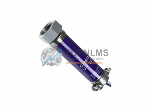
Original Honeywell C7027A1064/C7027A1072 UV Flame Sensor. C7027 Series compatible spare for industrial burner management. Fast shipping, 12-month warranty.
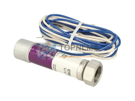
Honeywell CSNS300M-500 closed-loop Hall-effect current sensor, 300A/±500A. Rugged, EMI-resistant, PLC/DCS compatible. In stock, tested, 12-month warranty.
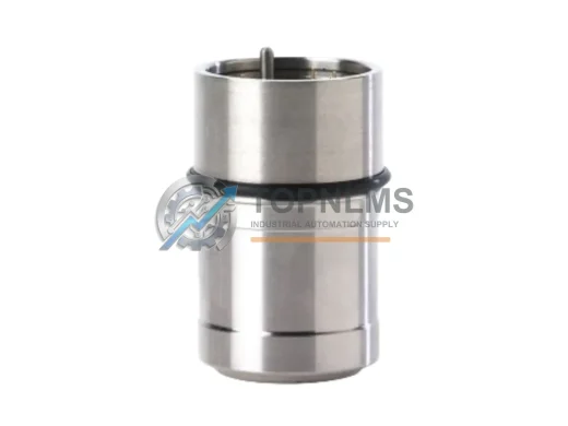
Honeywell SPXCDXSFXSS catalytic bead LEL sensor cartridge for XCD fixed gas detectors. Rugged, reliable, in stock. 12-month warranty. Fast global shipping.
Click Quote This Model and the Part Number field will auto-fill with C7035A1023 C7035A1064.