
GE
GE TGT-AIOV-8-0 Ruggedized Analog Voltage I/O Module
TGT-AIOV-8-0GE TGT-AIOV-8-0 Triconex TMR 8-channel analog voltage safety I/O module. Ruggedized for harsh environments. In stock, tested, 12-month warranty. Fast shipping.
Request availability, condition, lead time and export shipping details for DS200DTBBG1AAA.
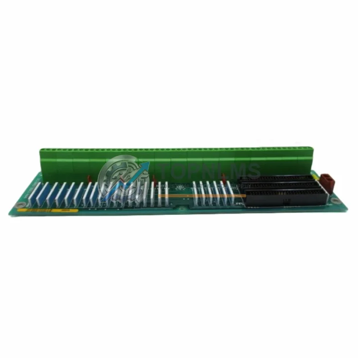
Send this exact part number, quantity and destination country. TOPNLMS will confirm availability, condition and export lead time before quotation.
The GE DS200DTBBG1AAA Relay Output Terminal Board is a critical I/O interface component within the GE Speedtronic Mark V and Mark VI turbine control platform. As GE progressively phases out legacy Mark V hardware, plant engineers and procurement teams face mounting pressure to source verified replacement boards that maintain full backward compatibility with existing wiring harnesses, relay logic, and control cabinet layouts. TOPNLMS supplies the DS200DTBBG1AAA as a direct drop-in replacement, fully tested and backed by a 12-month warranty, enabling facilities to extend the operational life of their Speedtronic control systems without committing to a full platform migration.
The DS200DTBBG1AAA serves as the relay output termination point for the Mark V DTBA/DTBB board set, interfacing discrete relay contact outputs to field devices such as solenoid valves, motor starters, and trip relays. In a typical Mark V architecture, this board is mounted in the R, S, or T controller core and connects directly to the VCMI or VCRC I/O processor cards. When replacing a failed or end-of-life DS200DTBBG1AAA, the physical connector pinout, DIN rail mounting footprint, and relay coil voltage specifications remain identical to the original GE factory design, ensuring zero rewiring is required at the terminal strip level.
For sites running the Mark VI Speedtronic platform, the DS200DTBBG1AAA is equally applicable in hybrid retrofit scenarios where Mark V I/O terminal boards are retained while the core controller is upgraded to a Mark VIe or Mark VIeS architecture. In these configurations, the terminal board continues to serve as the field-side wiring anchor, while the I/O pack — such as the IS200TRLYH1C Relay Output I/O Pack — is updated to communicate over the IONet Ethernet backbone. This approach dramatically reduces field rewiring costs and minimizes the risk of introducing wiring errors during a live plant upgrade.
Procurement teams evaluating this replacement should also consider the broader ecosystem of boards that typically fail or require simultaneous replacement during a Mark V service event. The DS200DTBAG1AAA (the companion DTBA terminal board) is frequently replaced alongside the DS200DTBBG1AAA, as both boards share the same backplane connector and are subject to identical thermal and vibration stress cycles. Similarly, the DS200SDCCG3A Speed Detector Control Card and the DS200TCQAG1BHF Analog I/O Terminal Board are common co-failure components in aging Mark V cabinets and should be inspected or pre-staged as spares during any planned outage.
Communication integrity is another key consideration during a Speedtronic upgrade. The Mark V relies on the proprietary ARCNET serial communication protocol between the R, S, and T controllers and the C core. When replacing terminal boards, it is essential to verify that the ARCNET coaxial cabling and the associated DS200SLCCG3A LAN Communication Card remain undisturbed, as any disruption to the ARCNET ring can cause a full turbine trip. For Mark VI systems transitioning to IONet, the IS200IOCIH1A I/O Controller Interface Card should be verified for firmware compatibility with the replacement terminal board assembly.
Power supply integrity is equally critical. The Mark V control cabinet typically operates on a redundant 28 VDC power bus supplied by the DS200PCCAG1A Power Supply Card. Before installing a replacement DS200DTBBG1AAA, technicians should verify bus voltage stability and inspect the power distribution fuse block for signs of thermal damage, which is a common root cause of relay output board failures. For Mark VI cabinets, the IS200EPCTG1A Ethernet Power Controller Terminal Board governs power sequencing and should be confirmed operational prior to commissioning the replacement board.
Physical installation of the DS200DTBBG1AAA requires no special tooling. The board seats into the Mark V I/O card cage using the standard GE Speedtronic guide rail system, and the field wiring terminal strip accepts 14–22 AWG conductors with standard ring or fork lugs. Cabinet space requirements are identical to the original board, making this a true form-fit-function replacement. For sites with limited cabinet access or restricted outage windows, TOPNLMS can pre-configure and bench-test the board against customer-supplied relay logic specifications prior to shipment, reducing on-site commissioning time to under two hours in most cases.
All DS200DTBBG1AAA units supplied by TOPNLMS are sourced from verified industrial surplus channels, subjected to a multi-point functional test protocol covering relay coil continuity, contact resistance, insulation resistance, and connector integrity, and shipped with full test documentation. Units are packaged in anti-static ESD bags with foam-lined cartons suitable for international air freight. Standard lead time from our Xiamen warehouse is 3–7 business days for stocked units, with express DHL/FedEx options available for emergency outage support.
| Parameter | DS200DTBBG1AAA (This Unit) | Legacy / Replaced Unit |
|---|---|---|
| Compatible Platform | GE Mark V, Mark VI Speedtronic | GE Mark V Speedtronic |
| Board Function | Relay Output Terminal Board (DTBB) | Relay Output Terminal Board (DTBB) |
| Connector Interface | Original GE backplane connector — no adapter required | Same pinout — direct swap |
| Relay Output Channels | Per OEM specification | Per OEM specification |
| Communication Protocol | ARCNET (Mark V) / IONet compatible (Mark VI hybrid) | ARCNET |
| Mounting | Standard GE Speedtronic card cage guide rail | Same — no cabinet modification |
| Power Requirement | 28 VDC via Mark V/VI power bus | 28 VDC |
| Wiring Compatibility | 14–22 AWG, ring/fork lug terminal strip | Same — zero rewiring required |
| Installation Space | Identical form factor to OEM board | Same slot — no mechanical modification |
| Replacement Recommendation | Direct drop-in; inspect DS200DTBAG1AAA simultaneously | — |
| Warranty | 12 Months from date of shipment | — |
A successful DS200DTBBG1AAA replacement rarely occurs in isolation. During a planned Mark V service outage, experienced maintenance teams typically stage a coordinated set of replacement components to maximize uptime recovery and reduce the probability of a repeat failure within the same maintenance cycle. The DS200DTBAG1AAA DTBA terminal board is the most common co-replacement item, as it shares the same backplane slot group and is subject to identical aging mechanisms. The DS200SDCCG3A Speed Detector Control Card is another high-priority spare, particularly for gas turbine applications where speed signal integrity is critical to safe operation.
For facilities upgrading from Mark V to Mark VI or Mark VIe, the IS200TRLYH1C Relay Output I/O Pack provides the modern IONet-compatible relay output function that maps directly to the DS200DTBBG1AAA’s field wiring, allowing the terminal board to be retained while the control electronics are modernized. The IS200IOCIH1A I/O Controller Interface Card and the IS200EPCTG1A Ethernet Power Controller Terminal Board are essential components in this migration path and should be sourced and tested as a matched set.
On the power and communications side, the DS200PCCAG1A Power Supply Card and the DS200SLCCG3A LAN Communication Card are frequently inspected and replaced during the same outage window as the DTBB board set. Ensuring these components are in verified working condition before commissioning the replacement DS200DTBBG1AAA eliminates the most common sources of post-replacement fault codes. For HMI connectivity, the DS200TCQAG1BHF Analog I/O Terminal Board supports the operator interface signal chain and should be confirmed functional as part of the post-replacement loop check procedure.
Q: Does replacing the DS200DTBBG1AAA require any wiring changes at the field terminal strip?
A: No. The DS200DTBBG1AAA is a form-fit-function replacement for the original GE board. The field wiring terminal strip connector is identical, and no rewiring is required. Simply document the existing wiring layout with photographs before removal, seat the replacement board, and verify relay output continuity with a multimeter before returning the turbine to service.
Q: Will the replacement board work with our existing Mark V ARCNET communication ring?
A: Yes. The DS200DTBBG1AAA does not contain active ARCNET communication logic — it is a passive terminal board that interfaces with the active I/O processor cards. The ARCNET ring operates through the DS200SLCCG3A LAN Communication Card and is unaffected by a terminal board replacement, provided the backplane connectors are fully seated and the coaxial ARCNET cabling is not disturbed during the swap.
Q: Can this board be used in a Mark VI hybrid retrofit where the terminal boards are retained but the I/O packs are upgraded?
A: Yes. This is a well-established migration strategy. The DS200DTBBG1AAA continues to serve as the field-side wiring anchor, while the Mark VI IS200TRLYH1C Relay Output I/O Pack connects to the terminal board via the standard I/O pack interface. This approach preserves all existing field wiring and reduces retrofit risk significantly.
Q: What is the physical installation procedure and how long does it take?
A: The board slides into the Mark V card cage on the standard GE guide rail system and is secured with the OEM captive screw. With the cabinet de-energized and the field wiring documented, a trained technician can complete the physical swap in under 30 minutes. Post-installation loop checks and relay output verification typically add 60–90 minutes depending on the number of output channels in service.
Q: How do I verify the replacement board is functioning correctly after installation?
A: After seating the board and restoring power, navigate to the Mark V HMI diagnostic screen and verify that no DTBB-related fault codes are present. Force each relay output channel from the HMI and confirm field device response with a multimeter or lamp test. TOPNLMS provides a pre-shipment test report with each unit that documents the relay coil resistance and contact resistance values measured during our bench test, which can be used as a baseline for comparison.
Every DS200DTBBG1AAA supplied by TOPNLMS is covered by a 12-month warranty from the date of shipment. This warranty covers defects in materials and workmanship under normal operating conditions consistent with the GE Speedtronic Mark V/VI operating environment. Our pre-shipment test protocol includes relay coil continuity verification, contact resistance measurement, insulation resistance testing to 500 VDC, and full connector integrity inspection. A signed test report is included with every shipment.
In the event of a warranty claim, TOPNLMS provides a replacement unit advance shipment within 3 business days of claim confirmation, minimizing plant downtime. Our after-sales response team is reachable by email and phone during business hours (UTC+8), and emergency outage support inquiries receive priority handling. All units are shipped in ESD-safe packaging with foam-lined cartons and are insured for the full declared value during transit.
For bulk procurement, long-term spare parts agreements, or emergency outage support, contact our industrial sales team directly. We maintain standing inventory of the DS200DTBBG1AAA and related Mark V/VI components at our Xiamen warehouse to support rapid deployment across Asia-Pacific, Middle East, and European plant sites.
GE TGT-AIOV-8-0 Triconex TMR 8-channel analog voltage safety I/O module. Ruggedized for harsh environments. In stock, tested, 12-month warranty. Fast shipping.
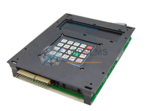
GE NP 104X905BA603 ruggedized membrane keypad panel for Mark IV/V turbine control. EMI-resistant, industrial-grade. In stock, tested, 12-month warranty.
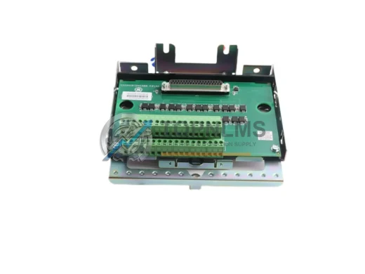
GE IS230SNRTH2A RTD Input Module for Mark VI turbine control. Drop-in replacement for IS200SRTDH2ACB. 12-month warranty, fast global shipping from TOPNLMS.
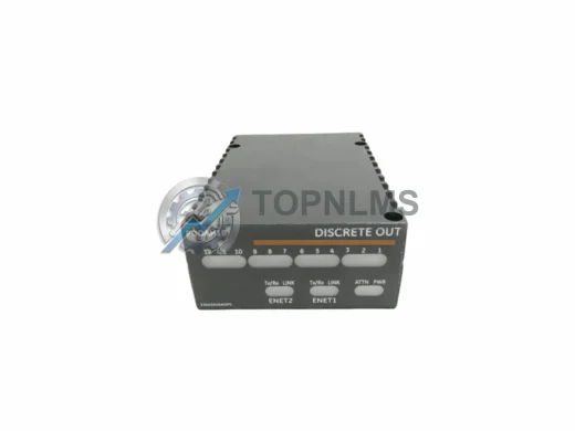
GE IS220YSILS1B ruggedized discrete output module for Mark VI Speedtronic. In stock, tested, 12-month warranty. Fast shipping from TOPNLMS.
Click Quote This Model and the Part Number field will auto-fill with DS200DTBBG1AAA.