Semikron
SEMIKRON SEMIX353GB126V1 Ruggedized IGBT Module
SEMIX353GB126V1SEMIKRON SEMIX353GB126V1 dual IGBT half-bridge module, 1200V/353A, SEMiX series. In stock, tested, 12-month warranty. Fast global shipping from TOPNLMS.
Request availability, condition, lead time and export shipping details for 101VMEJ106-9001.
Send this exact part number, quantity and destination country. TOPNLMS will confirm availability, condition and export lead time before quotation.
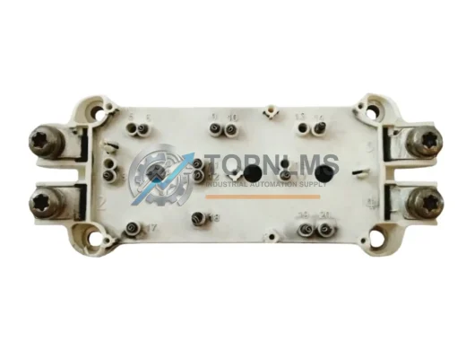
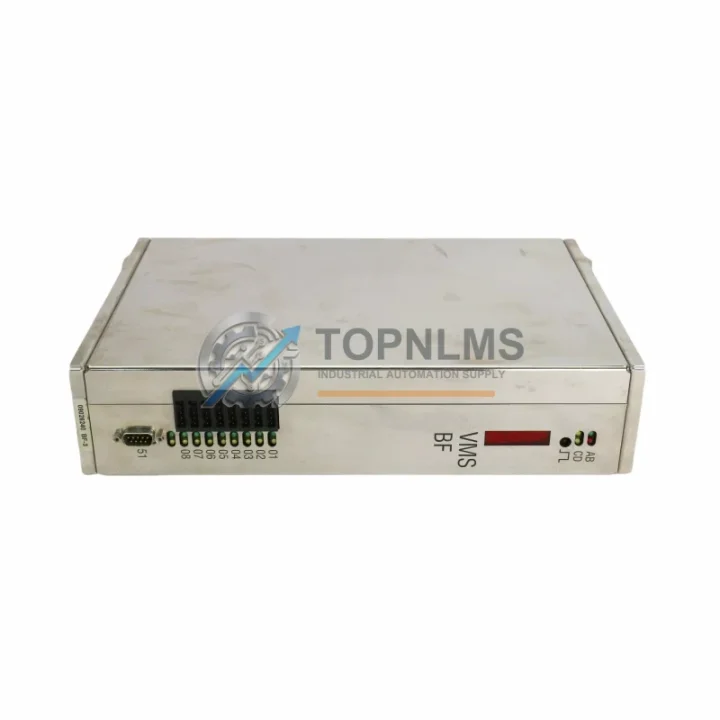
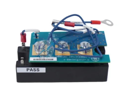
The CEIA P2 MB 5500CPU Power Cube — part number 101VMEJ106-9001, assembly references 810-800081-012, PW3-32/900, and HTR PW3-45/900 — is a precision power and CPU module at the heart of CEIA’s industrial metal detection platform. As production lines age and original CEIA P2 MB Series components approach end-of-life or become increasingly difficult to source, plant engineers and maintenance teams face mounting pressure to restore detector uptime without committing to a full system overhaul. This listing addresses that challenge directly: a verified, tested replacement module that slots into your existing P2 MB chassis with minimal disruption to wiring, programming, or physical installation.
The P2 MB 5500CPU integrates the central processing unit and regulated power distribution functions into a single compact cube form factor. It supplies conditioned DC power rails to the detector’s analog signal boards, digital I/O interface cards, and communication sub-assemblies. When this module fails or degrades, the entire detection line halts — making rapid, reliable replacement a critical procurement priority. Our stock is sourced from authorized distribution channels and subject to incoming inspection before dispatch.
For facilities running legacy CEIA THS/21 or CEIA THS/MS Series metal detectors alongside P2 MB-based systems, this module is frequently the missing link in a broader retrofit program. Engineers migrating from older CEIA GEN2 detector platforms to the P2 MB architecture will find that the 5500CPU’s power architecture is backward-compatible with the existing conveyor interface wiring harness, reducing re-cabling labor significantly. The module’s regulated output is also compatible with CEIA’s standard I/O expansion boards, including digital reject output relays and product-learn memory cards used in food and pharmaceutical inspection lines.
When planning a controlled replacement, maintenance teams typically stage the following alongside the 5500CPU module: the CEIA P2 MB Analog Signal Board (for baseline signal recalibration after module swap), the CEIA P2 MB Digital I/O Interface Card (to verify reject output continuity), and the CEIA P2 MB Communication Module (for RS-232 or RS-485 line integration with upstream SCADA or PLC systems). In facilities where the detector feeds data to a Siemens S7-300 or Allen-Bradley ControlLogix PLC via Profibus DP or DeviceNet, confirming the communication module firmware version before swapping the 5500CPU is strongly recommended to avoid protocol handshake errors on restart.
Physical installation follows the standard P2 MB cube-rail mounting procedure. The module slides into the detector’s internal chassis rail and locks with the original retention clip — no drilling, no bracket modification. Power input terminals accept the existing 24 VDC or 110/230 VAC supply wiring without re-termination, provided the supply cable gauge meets CEIA’s original specification. Thermal management is handled by the module’s integrated heater circuit (HTR PW3-45/900), which maintains stable operating temperature in cold-store or outdoor enclosure environments without requiring external heat trace.
For sites operating CEIA detectors inside stainless-steel wash-down enclosures or IP65-rated control cabinets, the module’s compact footprint preserves the original cabinet layout. No additional DIN rail space is consumed, and the existing cable management channels remain undisturbed. This is particularly relevant in meat processing and dairy facilities where enclosure integrity and hygiene compliance are non-negotiable during maintenance windows.
Post-installation commissioning follows CEIA’s standard product-learn sequence. The 5500CPU retains no product memory after replacement, so a fresh learn cycle is required for each product type running on the line. This process typically takes 15–30 minutes per product and can be completed by a trained operator without specialist CEIA service tools. For facilities with complex multi-product programs stored on a CEIA P2 MB Memory Card, backing up the existing program data before module removal is strongly advised.
In multi-detector installations — for example, a production line running three CEIA THS/21E heads in series — replacing a single 5500CPU module does not affect the calibration or reject logic of adjacent detector heads, provided the line controller (typically a CEIA Line Controller LC/01 or equivalent) is not reset during the swap. This allows maintenance to be performed during a scheduled micro-stop without triggering a full-line recalibration event.
Procurement teams evaluating this replacement should also consider holding a spare CEIA P2 MB Power Supply Board PW3-32/900 in local inventory. This board works in tandem with the 5500CPU and is subject to similar wear patterns in high-cycle production environments. Stocking both components reduces the risk of a secondary failure extending downtime beyond the initial repair window.
All units dispatched from our Xiamen warehouse are individually tested under load prior to packaging. Each module is shipped in anti-static protective packaging with a serialized inspection record. Standard dispatch lead time is 1–3 business days for in-stock units, with express DHL or FedEx options available for urgent requirements. Import documentation, including commercial invoice and packing list, is prepared to support customs clearance in EU, US, Southeast Asian, and Middle Eastern markets.
| Parameter | Legacy / OEM Reference | This Replacement Unit |
|---|---|---|
| Part Number | 101VMEJ106-9001 (OEM) | 101VMEJ106-9001 (Compatible Replacement) |
| Assembly Reference | 810-800081-012 | 810-800081-012 Compatible |
| Power Supply Sub-Assembly | PW3-32/900 | PW3-32/900 Compatible |
| Heater Circuit | HTR PW3-45/900 | HTR PW3-45/900 Compatible |
| Platform Series | CEIA P2 MB Series | CEIA P2 MB Series |
| CPU Architecture | 5500CPU | 5500CPU |
| Mounting | Cube-rail, internal chassis | Cube-rail, internal chassis (direct fit) |
| Power Input | 24 VDC / 110–230 VAC | 24 VDC / 110–230 VAC (no re-wiring required) |
| Communication Interface | RS-232 / RS-485 (via comm module) | RS-232 / RS-485 Compatible |
| Operating Environment | Cold-store / wash-down / IP65 enclosure | Same — integrated heater circuit retained |
| Installation Modification | N/A | None required — direct swap |
| Warranty | OEM (expired / EOL) | 12-Month Warranty from TOPNLMS |
A successful P2 MB 5500CPU replacement rarely happens in isolation. In practice, the swap is most reliable when coordinated with a review of adjacent modules that share the same power bus or communication backbone. The CEIA P2 MB Analog Signal Board should be recalibrated immediately after the CPU module is replaced, as the new module resets the signal baseline. The CEIA P2 MB Digital I/O Interface Card governs reject output relay logic and should be verified for continuity before the line resumes production.
For facilities integrating the detector into a broader automation architecture, the CEIA P2 MB Communication Module (RS-232/RS-485) bridges the detector to upstream Siemens S7 PLCs, Mitsubishi MELSEC controllers, or Omron CJ-series systems via standard serial protocols. Where Profibus DP integration is required, a CEIA Profibus DP Gateway Module may be inserted between the detector and the fieldbus network without modifying the 5500CPU configuration.
Power integrity is equally important. The CEIA P2 MB Power Supply Board PW3-32/900 works in tandem with the 5500CPU and should be inspected — and ideally replaced as a paired unit — in high-cycle environments. For installations in cold-store facilities, the HTR PW3-45/900 Heater Circuit Board maintains thermal stability and is already integrated into this module assembly.
Operators managing multi-head detection lines should also review the CEIA Line Controller LC/01, which coordinates reject logic across multiple detector heads and must remain online during a single-head module swap to avoid triggering a full-line fault. Finally, for sites requiring operator interface upgrades alongside the module replacement, a CEIA P2 MB HMI Panel or compatible third-party touchscreen HMI can be integrated without changes to the 5500CPU’s serial output configuration.
Q: Do I need to re-wire the power input terminals when replacing the 5500CPU module?
A: No. The replacement module uses the same terminal block layout and accepts the same 24 VDC or 110/230 VAC supply wiring as the original. No re-termination is required provided the existing cable gauge is within CEIA’s original specification.
Q: Will my existing product programs be retained after the module swap?
A: No. The 5500CPU does not retain product memory. Back up all product programs to a CEIA P2 MB Memory Card before removal, then reload after installation. A fresh product-learn cycle (15–30 minutes per product) is required.
Q: Is the replacement module compatible with Profibus DP or DeviceNet communication?
A: The 5500CPU itself communicates via RS-232/RS-485. Profibus DP or DeviceNet integration is handled by a separate gateway module. Confirm the gateway firmware version before swapping the CPU to avoid protocol handshake errors on restart.
Q: Can I install this module without modifying the detector enclosure or cabinet layout?
A: Yes. The module uses the original cube-rail mounting system and retains the same physical footprint. No drilling, bracket modification, or additional DIN rail space is required.
Q: Does the heater circuit (HTR PW3-45/900) function in cold-store environments?
A: Yes. The integrated heater circuit is part of this assembly and maintains stable operating temperature in cold-store, outdoor, and IP65-rated enclosure environments without external heat trace.
Q: How long does commissioning take after installation?
A: Physical installation typically takes under 30 minutes. Product-learn cycles add 15–30 minutes per product type. Full commissioning for a single-product line can be completed within one hour by a trained operator.
Every CEIA P2 MB 5500CPU Power Cube unit dispatched by TOPNLMS is covered by a 12-month warranty from the date of delivery. This warranty covers manufacturing defects, functional failure under normal operating conditions, and component-level faults identified during the warranty period.
Pre-shipment testing is performed on every unit under simulated load conditions. A serialized inspection record accompanies each shipment, documenting the test date, test parameters, and pass result. Units that do not meet our functional acceptance criteria are quarantined and not dispatched.
In the event of a warranty claim, TOPNLMS provides a replacement unit or full refund within the warranty period. Our after-sales response target is 24 hours for initial acknowledgment and 72 hours for resolution confirmation. Replacement units are dispatched with priority shipping at no additional cost to the buyer.
For urgent procurement requirements — including emergency breakdown situations — express dispatch via DHL Express or FedEx International Priority is available for in-stock units, with same-day or next-business-day cutoff depending on order confirmation time. All shipments include full commercial invoice, packing list, and country-of-origin documentation to support customs clearance in your destination market.
TOPNLMS maintains a dedicated after-sales support channel for industrial automation components. For technical pre-sales questions, compatibility verification, or post-delivery support, contact our engineering team directly.
© 2026 TOPNLMS. All rights reserved.
Original Source: https://topnlms.com
Contact: [email protected] | +86 18359293191
SEMIKRON SEMIX353GB126V1 dual IGBT half-bridge module, 1200V/353A, SEMiX series. In stock, tested, 12-month warranty. Fast global shipping from TOPNLMS.
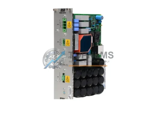
ETEL DSO-PWR111C-000A rack power module replacement for DSO Drive System. Drop-in upgrade, 12-month warranty, tested & fast shipping. Original spare.
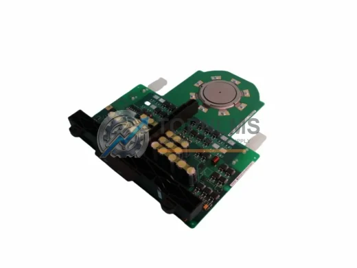
ABB 3BHL000986P3012 / 5SDD2545L0001 IGCT press-pack power module. Ruggedized for harsh industrial environments. In stock, tested, 12-month warranty. Fast shipping.
GE RE421REPAH1APR4 ruggedized thyristor power control module. In stock, tested, 12-month warranty. Fast shipping. Contact [email protected].
Click Quote This Model and the Part Number field will auto-fill with 101VMEJ106-9001.