Product Overview
Bently Nevada 190501-21-00-01 Velomitor CT Upgrade Solution: Seamless Transition from Legacy Vibration Monitoring Systems
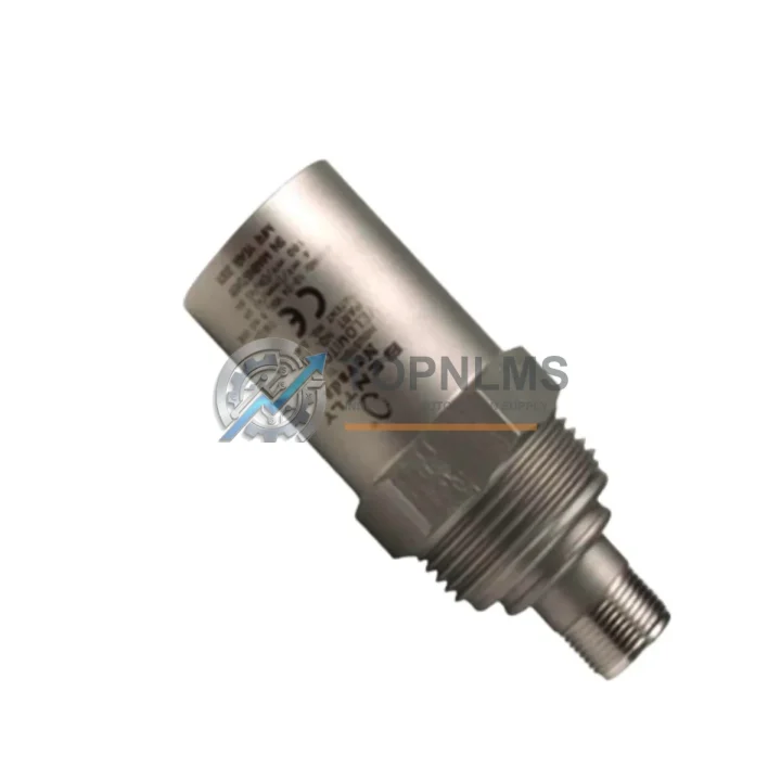
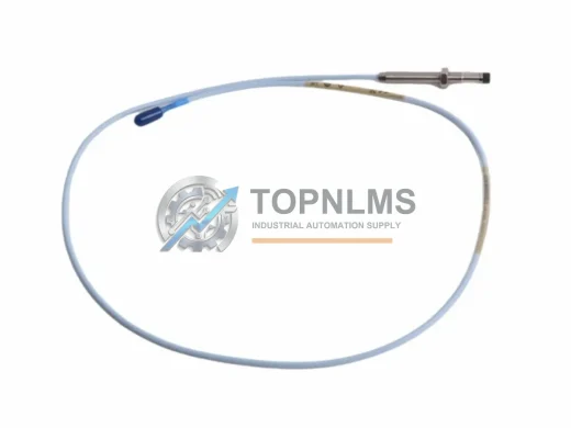
The Bently Nevada 190501-21-00-01 is a Velomitor CT Series seismic velocity transducer engineered for continuous machinery protection and condition monitoring in rotating equipment applications. As legacy vibration monitoring installations age and original Bently Nevada Velomitor CT units approach end-of-service life, plant engineers and reliability teams face the critical challenge of sourcing a verified replacement that maintains signal integrity, wiring compatibility, and seamless integration with existing System 1 or 3500 Series machinery protection racks.
This product page is dedicated to engineers planning a controlled migration from discontinued or aging velocity transducer installations to the 190501-21-00-01 — covering wiring compatibility, communication architecture, physical mounting, power supply requirements, and commissioning guidance to minimize planned and unplanned downtime.
Compatibility Comparison Table
| Parameter |
Legacy / Predecessor Models |
190501-21-00-01 (Velomitor CT) |
| Series |
Velomitor (Standard), 330500 Series |
Velomitor CT (Compact) |
| Output Signal |
Velocity (mV/mm/s or mV/in/s) |
Velocity — same signal convention, direct drop-in |
| Connector / Wiring |
2-pin MIL-C-5015 or equivalent |
Compatible 2-wire interface; field wiring reuse possible |
| Mounting |
1/4-28 UNF stud or adhesive pad |
1/4-28 UNF stud mount — same footprint |
| Power Supply |
18–30 VDC (loop powered) |
18–30 VDC — no power supply upgrade required |
| Frequency Range |
2–1000 Hz (typical) |
2–1000 Hz — identical measurement bandwidth |
| Rack Compatibility |
Bently Nevada 3500/42M, 3500/45, 3300 Series |
Fully compatible with 3500 Series I/O modules |
| Communication Protocol |
Analog 4–20 mA / voltage output |
Analog output — no protocol conversion needed |
| Hazardous Area Rating |
ATEX / IECEx (model dependent) |
Verify suffix code for Ex-rated variants |
| Replacement Recommendation |
Direct replacement for 190501 standard Velomitor |
✔ Recommended upgrade path |
| Warranty |
— |
12-Month Warranty (TOPNLMS) |
Seamless Upgrade Solutions
A successful migration from a legacy vibration monitoring system to the Bently Nevada 190501-21-00-01 rarely involves a single component swap. In practice, plant engineers undertaking a Velomitor CT retrofit will simultaneously evaluate the condition of adjacent system components to ensure the entire signal chain is reliable and future-proof.
In installations built around the Bently Nevada 3500 Series machinery protection system, the 190501-21-00-01 interfaces directly with the 3500/42M Proximitor/Seismic Monitor or the 3500/45 Position Monitor I/O modules. If these monitor cards are also approaching end-of-life or showing calibration drift, replacing them in the same maintenance window eliminates the risk of a second unplanned outage. The 3500/20 Rack Interface Module (RIM) governs Modbus TCP or RS-232 communication to the DCS or SCADA layer — verifying its firmware version during the transducer swap is a low-cost step that prevents protocol mismatches downstream.
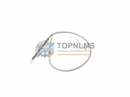
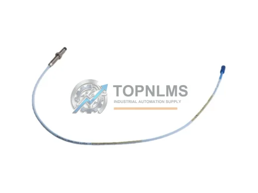
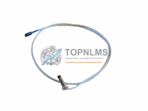
For installations where the existing field cable runs are long or routed through electrically noisy environments, engineers often add a Bently Nevada 3500/15 Power Supply Module or a dedicated signal isolator to maintain signal-to-noise ratio after the transducer replacement. In older plants where the junction box terminal blocks have corroded or where the original 330130 Proximitor Extension Cable is degraded, replacing the cable assembly alongside the 190501-21-00-01 is strongly recommended to avoid intermittent faults that are difficult to diagnose post-commissioning.
Where the machinery protection rack feeds a System 1 Evolution software platform or a third-party DCS such as an Emerson DeltaV or Honeywell Experion node, the analog output from the 190501-21-00-01 is received by the existing I/O card without any configuration change — the signal scaling and alarm setpoints defined in the rack monitor module remain valid. However, if the site is simultaneously upgrading from System 1 Classic to System 1 Evolution, it is advisable to audit the 3500/22M Transient Data Interface (TDI) module to confirm compatibility with the new software version.
In turbomachinery and compressor train applications, the Velomitor CT transducer is frequently installed alongside Bently Nevada 330180 Series proximity probes and 3300 XL 8mm proximity transducer systems for combined radial vibration and axial position monitoring. Coordinating the replacement of both sensor types during a planned turnaround reduces total installation labor and ensures that all channels are calibrated to the same reference baseline before restart.
For sites that have migrated their control architecture to a modern PLC platform — such as a Rockwell Automation ControlLogix or Siemens S7-400 — and are using the 3500 rack as a standalone protection layer with hardwired trip outputs, the 190501-21-00-01 replacement requires no changes to the PLC program or I/O mapping. The relay output module in the 3500 rack handles all trip logic independently, and the PLC receives only the healthy/trip status via discrete wiring.
Retrofit Guidance FAQ
Q: Can I reuse the existing field wiring when replacing the old Velomitor with the 190501-21-00-01?
A: In most cases, yes. The 190501-21-00-01 uses the same 2-wire loop-powered interface as the standard Velomitor series. Inspect the existing cable for insulation damage and verify continuity before reuse. If the cable run exceeds 300 meters or passes through high-EMI zones, consider replacing with a shielded twisted-pair instrument cable.
Q: Do I need to modify the 3500 Series monitor configuration after installing the 190501-21-00-01?
A: No configuration changes are required if the replacement transducer has the same sensitivity (mV/mm/s) as the original. Verify the sensitivity value on the transducer label and confirm it matches the value entered in the 3500/42M or 3500/45 monitor card configuration. If the sensitivity differs, update the scale factor in the monitor using Rack Configuration Software (RCS).
Q: Is the 190501-21-00-01 compatible with ATEX Zone 1 or Zone 2 hazardous area installations?
A: Hazardous area approval depends on the specific suffix code of the ordered unit. Confirm the Ex rating on the product label and the associated Zener barrier or galvanic isolator in the safe area before installation. Contact TOPNLMS to confirm the correct variant for your hazardous area classification.
Q: How much physical space does the Velomitor CT require compared to the standard Velomitor?
A: The Velomitor CT (Compact) form factor is smaller than the standard Velomitor housing, making it suitable for installations with restricted access or tight mounting clearances. The 1/4-28 UNF stud mount pattern is identical, so no re-drilling or bracket modification is required.
Q: Can the 190501-21-00-01 communicate directly with a DCS or SCADA system?
A: The transducer itself outputs an analog velocity signal. Communication to DCS or SCADA is handled by the 3500 Series rack monitor module (e.g., via Modbus TCP through the 3500/20 RIM). No direct digital communication interface is present on the transducer.
Q: What is the recommended commissioning procedure after installation?
A: After mechanical installation and wiring, power up the 3500 rack and verify the OK LED status on the monitor card. Use a calibrated shaker or reference signal to confirm the transducer output matches the expected sensitivity. Record the baseline vibration reading and compare against the pre-replacement baseline to confirm correct installation.
Warranty Assurance
Every Bently Nevada 190501-21-00-01 unit shipped by TOPNLMS is covered by a 12-month warranty from the date of delivery. Prior to shipment, each unit undergoes functional verification including output signal check, connector integrity inspection, and visual examination for physical damage. Units that fail to meet specification are quarantined and not shipped.
In the event of a warranty claim, TOPNLMS provides a replacement unit or full refund within the warranty period. Our after-sales response team is reachable within one business day for technical queries, warranty registration, and return merchandise authorization (RMA) processing. We maintain buffer stock of the 190501-21-00-01 to support urgent replacement orders with same-day or next-day dispatch from our Xiamen warehouse.
For B2B procurement teams, we can provide a Certificate of Conformance (CoC), packing list, and commercial invoice with each shipment to support your incoming inspection and asset management processes. Volume pricing and blanket order arrangements are available for MRO and spare parts programs.