Product Overview
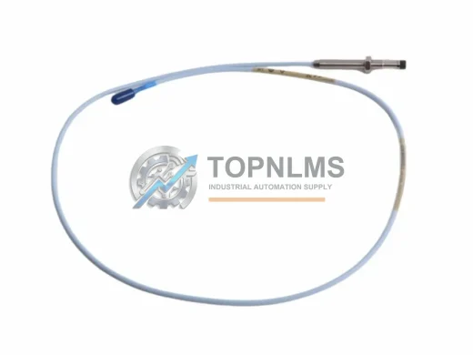
Bently Nevada 190501-13-00-00 Velomitor CT Upgrade Solution: Seamless Transition from Legacy Vibration Monitoring
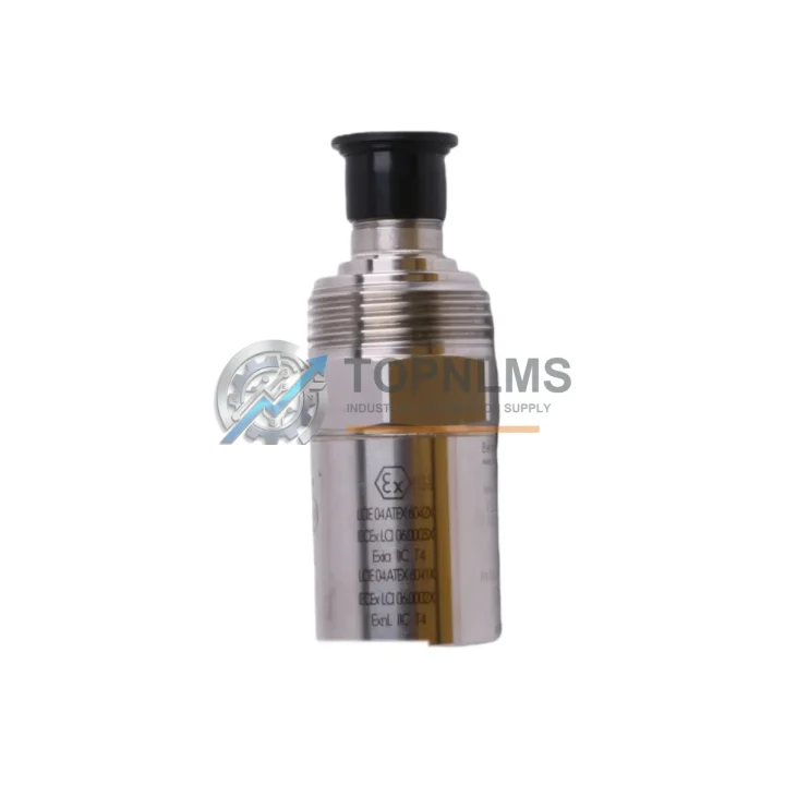
The Bently Nevada 190501-13-00-00 is a Velomitor CT Series piezoelectric velocity transducer engineered for continuous vibration monitoring on rotating machinery including turbines, compressors, pumps, and motors. As legacy Velomitor CT units reach end-of-service life or become difficult to source through OEM channels, plant engineers and reliability teams face a critical decision: how to maintain uninterrupted condition monitoring without triggering a full system overhaul.
This replacement and upgrade solution is designed specifically for facilities running Bently Nevada 3500 Series rack-based monitoring systems, System 1 condition monitoring software, or legacy 7200 Series proximity systems that have been partially migrated. The 190501-13-00-00 delivers a 4–20 mA velocity output signal compatible with existing field wiring, junction boxes, and barrier strips — meaning no rewiring of the marshalling cabinet is required in most retrofit scenarios.
When replacing a failed or aging 190501-13-00-00, technicians typically find that the existing two-conductor shielded cable, conduit routing, and terminal block assignments can be reused without modification. The transducer’s M8 or equivalent mounting thread and compact cylindrical housing fit the original mounting boss on the machine casing, eliminating the need to re-machine bearing housings or fabricate new brackets. This physical compatibility dramatically reduces installation labor and minimizes the machine downtime window to a single planned maintenance interval.
For sites migrating from older Velomitor XA or standard Velomitor units to the Velomitor CT platform, the key upgrade benefit is the built-in signal conditioning circuitry that eliminates the need for a separate signal conditioner module in the control cabinet. The 190501-13-00-00 outputs a conditioned 4–20 mA loop-powered signal directly readable by the Bently Nevada 3500/42M Velocity/Acceleration Monitor or equivalent I/O cards in a DCS such as the Emerson DeltaV or Honeywell Experion PKS. This simplifies the signal chain and reduces the number of field devices requiring calibration during commissioning.
In multi-machine train applications — for example, a gas turbine driving a centrifugal compressor with an intermediate gearbox — it is common to deploy multiple Velomitor CT transducers alongside Bently Nevada 3300 XL 8mm proximity probes for radial shaft vibration and a Bently Nevada 330180 thrust position probe for axial displacement. The 190501-13-00-00 complements these proximity-based measurements by capturing casing velocity, providing a complete vibration signature for the entire machine train within a single 3500 Series rack. Replacing one transducer in this configuration does not require reconfiguring the rack or modifying the System 1 database, provided the channel assignment and engineering unit scaling remain unchanged.
For facilities operating older standalone vibration panels or portable data collectors, the 190501-13-00-00 can also be wired to a Bently Nevada Trendmaster 2000 or a third-party vibration transmitter input card, provided the input accepts a 4–20 mA velocity signal. In such cases, the loop supply voltage (typically 24 VDC from the panel power supply or a dedicated DIN-rail PSU) must be verified against the transducer’s operating voltage range before installation. A Bently Nevada 3500/05 power supply module or equivalent 24 VDC DIN-rail unit is the standard field-verified power source for this transducer family.
During commissioning after replacement, the standard verification procedure involves a bump test or reference comparison against a calibrated handheld vibration meter to confirm the output signal tracks correctly before the machine is returned to service. The 190501-13-00-00’s factory calibration certificate, supplied with each unit, provides the sensitivity value (mV per mm/s or mA per mm/s) required to configure the monitor channel scaling in the 3500 rack or DCS I/O configuration tool. No field calibration equipment beyond a standard multimeter and the existing monitor configuration software is required for a like-for-like replacement.
For procurement teams managing spare parts inventory, stocking the 190501-13-00-00 alongside related consumables such as Bently Nevada 330130 proximity probe extension cables, 3500/92 communication gateway modules, and standard M12 field connector assemblies ensures that a complete vibration monitoring restoration can be executed within a single maintenance window. Each unit shipped from our Xiamen warehouse is individually tested, serialized, and accompanied by a factory test report, reducing incoming inspection time at the plant.
Compatibility Comparison Table
| Parameter |
Legacy / Replaced Model |
190501-13-00-00 (Velomitor CT) |
| Model / SKU |
Velomitor XA / 190501-01-00-00 (typical) |
190501-13-00-00 |
| Output Signal |
Voltage (AC, requires external conditioner) |
4–20 mA (loop-powered, conditioned) |
| Wiring Compatibility |
2-conductor shielded cable |
2-conductor shielded cable (direct reuse) |
| Mounting Thread |
M8 × 1.25 or 1/4-28 UNF |
M8 × 1.25 (verify per installation) |
| Supply Voltage |
18–30 VDC (external conditioner) |
18–30 VDC (loop supply) |
| Frequency Range |
10–1000 Hz (typical) |
10–1000 Hz |
| Compatible Monitor |
3500/42M, 7200 Series |
3500/42M, 3500/42, DCS 4–20 mA input |
| Communication Protocol |
Analog (4–20 mA or voltage) |
Analog 4–20 mA |
| Installation Space |
Standard cylindrical housing |
Same form factor — no bracket modification |
| Replacement Complexity |
— |
Drop-in; no rewiring or rack reconfiguration |
| Warranty |
— |
12-Month Warranty (from ship date) |
Seamless Upgrade Solutions
A successful migration to the 190501-13-00-00 rarely involves a single component in isolation. In practice, the replacement is most efficient when coordinated with a review of adjacent field devices and rack modules. The Bently Nevada 3500/42M Velocity/Acceleration Monitor is the primary rack card that receives the transducer’s 4–20 mA output; if the existing card is also aging, replacing both simultaneously avoids a second machine outage. Similarly, the 3500/05 Power Supply module should be inspected for output voltage stability, as a marginal supply can cause erratic readings from the new transducer even when the transducer itself is functioning correctly.
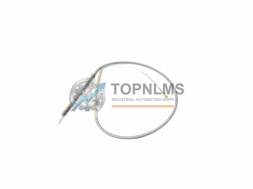
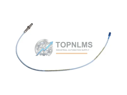
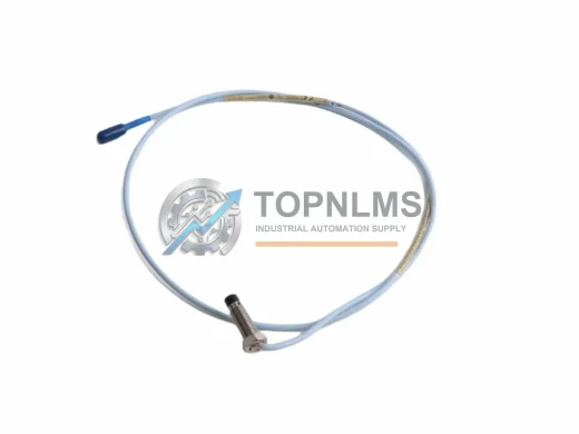
In the field junction box, Bently Nevada 3500/92 or equivalent communication gateway modules handle the Modbus RTU or Ethernet/IP data path from the rack to the DCS historian. If the site is also upgrading from a serial Modbus link to an Ethernet-based architecture, replacing the gateway module concurrently with the transducer minimizes the number of separate commissioning events. For the signal cable run between the transducer and the junction box, Bently Nevada 330130 Series armored extension cables provide the correct impedance and shielding characteristics to maintain signal integrity over runs exceeding 30 meters.
Where the machine train also uses proximity probes for shaft vibration — such as Bently Nevada 3300 XL 8mm probes with 3300 XL extension cables and 3300 XL proximitor sensors — the 190501-13-00-00 integrates into the same 3500 rack without requiring a separate rack section, provided an available velocity/acceleration channel slot exists. For facilities that have already migrated shaft vibration monitoring to the 3500 platform but retained older casing vibration sensors, this transducer replacement completes the platform consolidation and simplifies spare parts management to a single rack family.
Finally, for sites where the HMI or operator workstation runs Bently Nevada System 1 software, the channel configuration for the replacement transducer can be updated in the System 1 database using the existing engineering unit and alarm setpoint values from the replaced unit, provided the sensitivity value from the new transducer’s calibration certificate is entered correctly. No additional software licenses or hardware keys are required for a like-for-like channel replacement.
Retrofit Guidance FAQ
Q: Can I reuse the existing field wiring when replacing the 190501-13-00-00?
A: Yes. The Velomitor CT uses a standard 2-conductor shielded cable with a loop-powered 4–20 mA signal. In most installations, the existing cable, conduit, and terminal block assignments can be reused without modification, provided the cable insulation and shield continuity are verified before reconnection.
Q: Does the replacement require changes to the 3500 rack configuration?
A: For a like-for-like replacement on the same channel, no rack reconfiguration is required. The channel scaling (sensitivity value) should be updated in the 3500 rack configuration software if the new transducer’s calibration certificate shows a different sensitivity than the original unit.
Q: Is the 190501-13-00-00 compatible with DCS 4–20 mA input cards?
A: Yes. The transducer outputs a standard 4–20 mA loop-powered signal compatible with any DCS or PLC analog input card that accepts a 4–20 mA current loop, including Emerson DeltaV, Honeywell Experion PKS, and Siemens PCS 7 AI modules.
Q: What is the physical mounting compatibility?
A: The 190501-13-00-00 uses an M8 × 1.25 mounting thread in a standard cylindrical housing. In most Velomitor CT installations, the existing mounting boss on the machine casing accepts the replacement unit directly. Verify the thread specification against your installation drawing before ordering.
Q: How long does commissioning take after replacement?
A: A trained instrumentation technician can typically complete a like-for-like replacement — including cable reconnection, loop verification, bump test, and alarm setpoint confirmation — within 2–4 hours, depending on machine accessibility and control room staffing.
Q: What supply voltage is required?
A: The transducer requires 18–30 VDC loop supply, typically provided by the 3500/05 power supply module or a dedicated 24 VDC DIN-rail PSU in the field junction box. Verify the loop supply voltage at the terminal block before connecting the new transducer.
Warranty Assurance
Every 190501-13-00-00 Velomitor CT transducer shipped by TOPNLMS carries a 12-month warranty from the date of shipment. Prior to dispatch, each unit undergoes individual functional testing including output signal verification, insulation resistance check, and physical inspection. A factory test report and calibration certificate are included with every shipment.
In the event of a warranty claim, TOPNLMS provides a replacement unit or full refund within the warranty period, subject to inspection of the returned item. Our technical team is available to support installation, commissioning, and troubleshooting queries via email at [email protected] or by phone at +86 18359293191. Standard lead time from our Xiamen warehouse is 3–7 business days for stocked units, with express shipping options available for urgent plant maintenance requirements.
For procurement teams managing approved vendor lists or requiring documentation packages (test reports, certificates of conformance, or packing lists), these are available upon request at the time of order. Bulk orders for spare parts programs are supported with volume pricing and scheduled delivery agreements.
© 2026 TOPNLMS. All rights reserved.
Original Source: https://topnlms.com
Contact: [email protected] | +86 18359293191