Product Overview
Bently Nevada 190501-09-00-01 Original Industrial Spare Velomitor CT Compatible: System Stability & Maintenance Value
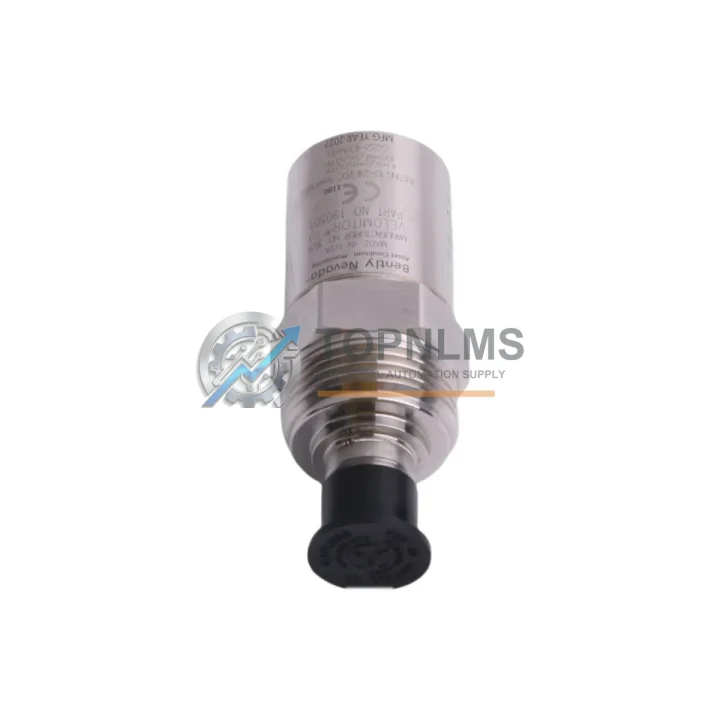
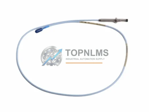
The Bently Nevada 190501-09-00-01 is a Velomitor CT Series piezoelectric velocity transducer engineered for continuous vibration monitoring in rotating machinery protection systems. As an original industrial spare part, it is a direct-fit replacement for existing Bently Nevada 3500 Series machinery protection installations, delivering the same signal fidelity, frequency response, and mechanical interface as the factory-installed unit — without requiring recalibration of the monitoring rack or modification of field wiring.
In industrial facilities where rotating equipment such as centrifugal compressors, steam turbines, pumps, and fans operate around the clock, the velocity transducer is a first-line diagnostic sensor. When this component degrades or fails, the machinery protection system loses its ability to detect bearing wear, rotor imbalance, misalignment, and structural resonance — conditions that, left undetected, escalate into unplanned shutdowns, catastrophic equipment damage, and significant production losses. Maintaining a verified spare of the 190501-09-00-01 in your critical-parts inventory is a foundational element of any credible predictive maintenance program.
This unit ships fully tested, with each transducer verified for sensitivity, frequency linearity, and output impedance prior to dispatch. A 12-month warranty is included from the date of shipment, covering manufacturing defects and performance deviations from published specifications.
Critical Technical Specs
| Parameter |
Specification |
| Part Number |
190501-09-00-01 |
| Brand / OEM |
Bently Nevada |
| Series |
Velomitor CT (Compact Top-exit) |
| Sensor Type |
Piezoelectric Velocity Transducer |
| Measurement Range |
0 to 50 in/s pk (0 to 1270 mm/s pk) |
| Frequency Response |
4.5 Hz to 5000 Hz (±3 dB) |
| Sensitivity |
100 mV/in/s (4 mV/mm/s) |
| Output Impedance |
≤ 3000 Ω |
| Operating Temperature |
-40°C to +121°C (-40°F to +250°F) |
| Housing Material |
316 Stainless Steel |
| Connector / Cable Exit |
Top-exit, 2-pin MIL-C-5015 style |
| Mounting Thread |
1/4-28 UNF (standard Bently Nevada mount) |
| Compatible Systems |
Bently Nevada 3500 Series Machinery Protection System |
| Country of Origin |
United States |
| Weight |
Approx. 320 g |
| Warranty |
12 Months from shipment date |
| Condition |
Original, new-in-box or fully tested surplus |
Preventive Maintenance Strategy
A velocity transducer replacement is rarely an isolated event. When a 190501-09-00-01 is flagged for replacement during a scheduled outage or condition-monitoring review, experienced maintenance engineers treat the intervention as an opportunity to audit the entire vibration monitoring loop and the surrounding control cabinet infrastructure.
Begin with the Bently Nevada 3500/42M Velocity Monitor module — the rack-mounted signal conditioner that receives the transducer output. If the transducer has been in service for more than five years, the monitor module’s input circuitry should be inspected for drift, and the alarm setpoints verified against current baseline data. At the same time, inspect the 3500/20 Rack Interface Module (RIM), which manages communication between the 3500 rack and the plant DCS or historian; a degraded RIM can mask valid transducer alarms at the supervisory level.
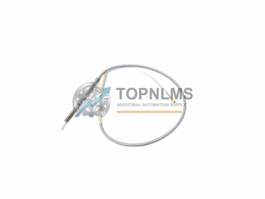
Field wiring integrity is equally critical. The Bently Nevada 330130 extension cable (or equivalent armored field cable) running from the transducer to the junction box should be checked for insulation resistance, shield continuity, and connector corrosion — particularly in high-vibration or high-temperature zones near turbine casings. A compromised cable introduces noise that mimics genuine vibration events, leading to nuisance trips or, worse, masking real fault signatures.
While the control cabinet is open, verify the condition of the 3500/15 Power Supply module. Power supply degradation is a leading cause of intermittent rack faults and is frequently overlooked during transducer-focused maintenance windows. If the facility operates redundant power feeds, test the automatic switchover function under load. Alongside the power supply, inspect the terminal barrier strips and field wiring terminal blocks within the junction box for loose connections, oxidation, and correct torque — loose terminals are a disproportionate source of spurious vibration alarms in long-running installations.
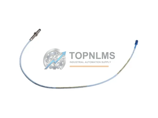
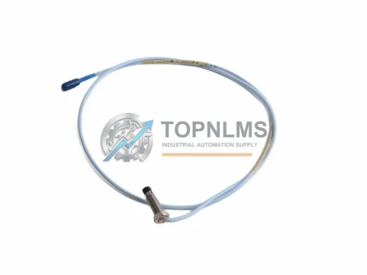
For facilities running a broader Bently Nevada ecosystem, this maintenance window is also the right time to cross-check the calibration status of any co-located 3300 XL 8mm proximity probes and extension cables monitoring shaft displacement on the same machine train. Velocity and displacement measurements are complementary; a machine that shows elevated velocity readings but normal displacement may indicate a structural resonance issue rather than a bearing fault — a distinction that requires both sensor types to be in calibration.
Finally, if the plant uses a System 1 Evolution or System 1 Condition Monitoring software platform, update the asset configuration to reflect the transducer replacement date and re-establish the baseline vibration signature after the machine returns to steady-state operation. Accurate baseline data is the foundation of effective predictive maintenance and directly reduces the risk of both missed faults and unnecessary interventions.
Stocking a minimum of one verified spare 190501-09-00-01 per critical machine train — alongside a spare 3500/42M monitor module and a pre-terminated field cable assembly — reduces mean time to repair (MTTR) for velocity monitoring failures from days to hours, a difference that is often measured in tens of thousands of dollars of avoided production loss per incident.
Strategic Replacement Solutions
The 190501-09-00-01 is a direct replacement for earlier Bently Nevada Velomitor models, including the 190501-01-00-01 and 190501-05-00-01 variants, which share the same mechanical footprint and electrical interface but differ in cable exit orientation or connector type. Facilities that standardized on these earlier part numbers during original equipment commissioning can transition to the 190501-09-00-01 without modifying the 3500 rack configuration, field junction boxes, or alarm setpoints — a significant advantage when managing aging machinery protection infrastructure.
For plants operating legacy Bently Nevada 7200 Series or 9000 Series monitoring systems, the Velomitor CT’s standard output impedance and sensitivity are compatible with most legacy monitor input specifications, though a signal conditioning review is recommended before installation. This cross-compatibility extends the useful life of existing monitoring infrastructure and defers the capital expenditure associated with full system upgrades — a compelling value proposition in facilities where budget cycles are long and equipment replacement windows are narrow.
The stainless steel housing and wide operating temperature range make the 190501-09-00-01 suitable for direct replacement in harsh environments including offshore platforms, petrochemical processing units, and power generation facilities where alternative sensor technologies may require additional environmental protection. The top-exit cable configuration simplifies installation in confined spaces where radial cable routing is impractical, reducing installation time and the risk of cable damage during commissioning.
Support FAQ
Q1: What is the expected service life of the 190501-09-00-01, and when should I plan for replacement?
Under normal operating conditions (continuous service, temperatures within specification, no mechanical shock events), the Velomitor CT is designed for a service life exceeding 10 years. However, for critical machinery protection applications, Bently Nevada and most reliability engineering standards recommend proactive replacement at 7–8 years or at the first sign of sensitivity drift, increased noise floor, or connector degradation — whichever comes first. Maintaining a spare in inventory ensures replacement can be executed during a planned outage rather than an emergency shutdown.
Q2: How do I verify compatibility with my existing 3500 Series rack before installation?
The 190501-09-00-01 is compatible with all 3500/42M Velocity Monitor modules and is electrically interchangeable with other Velomitor CT variants sharing the same sensitivity (100 mV/in/s) and output impedance (≤3000 Ω). Confirm the monitor module’s input configuration (single-ended vs. differential) and verify that the field cable connector type matches the transducer’s top-exit MIL-C-5015 style connector. No rack reconfiguration or software parameter changes are required for a like-for-like replacement.
Q3: What pre-shipment testing is performed, and what documentation is provided?
Each unit undergoes functional testing covering sensitivity verification, frequency response linearity across the rated bandwidth, and output impedance measurement prior to dispatch. A test report is available upon request. Units are shipped in anti-static, impact-protective packaging with a certificate of conformance. The 12-month warranty covers return-to-base repair or replacement for any unit that fails to meet published specifications under normal operating conditions.
Q4: Can this transducer be used as a direct field replacement without recalibrating the monitoring system?
Yes. Because the 190501-09-00-01 maintains the same sensitivity, frequency response, and mechanical interface as the original factory-installed unit, a like-for-like field replacement does not require recalibration of the 3500 rack or adjustment of alarm setpoints. After installation, it is good practice to verify the overall loop by performing a functional check at the monitor module and confirming that the baseline vibration reading at steady-state machine speed is consistent with the pre-replacement historical trend. Any significant deviation from the established baseline should be investigated before returning the machine to normal operation.