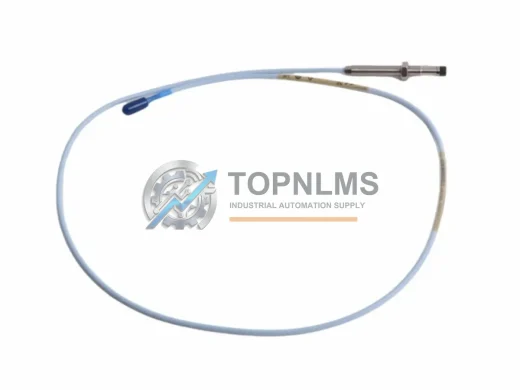
Product Overview
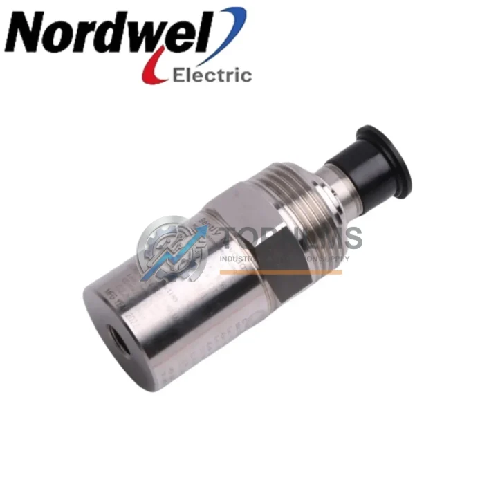
Bently Nevada 190501-02-99-01 Original Spare Velomitor CT Compatible: System Stability and Industrial Spare Maintenance Value
In rotating machinery protection and condition monitoring environments, the Bently Nevada 190501-02-99-01 Velomitor CT Piezoelectric Velocity Transducer is a mission-critical component. Unplanned downtime caused by a failed velocity transducer can cascade across an entire machinery protection system — triggering false shutdowns, masking real vibration anomalies, or leaving rotating assets unprotected. Stocking a verified original spare of the 190501-02-99-01 is one of the most cost-effective decisions a maintenance team can make for long-term system stability.
The Velomitor CT series is widely deployed in turbines, compressors, pumps, motors, and gearboxes across oil & gas, power generation, petrochemical, and heavy manufacturing facilities. Its piezoelectric sensing element delivers broadband velocity measurement with high sensitivity and low noise, making it the preferred transducer for seismic and casing vibration monitoring in Bently Nevada 3500 and System 1 machinery protection architectures.
Critical Technical Specs Table
| Parameter |
Specification |
| Part Number / SKU |
190501-02-99-01 |
| Brand |
Bently Nevada |
| Series |
Velomitor CT |
| Product Type |
Piezoelectric Velocity Transducer |
| Sensing Technology |
Piezoelectric (velocity output) |
| Measurement Range |
Seismic / casing vibration velocity |
| Frequency Response |
Approx. 2 Hz – 1,000 Hz (typical Velomitor CT range) |
| Output Signal |
Voltage proportional to velocity (mV/mm/s or mV/in/s) |
| Connector / Interface |
2-pin MIL-spec connector (compatible with Bently Nevada 3500 series) |
| Housing / Enclosure |
Stainless steel, IP67-rated (typical) |
| Mounting |
Threaded stud mount, side or top entry |
| Operating Temperature |
-40°C to +121°C (typical industrial range) |
| Compatible Systems |
Bently Nevada 3500 Machinery Protection System, System 1 |
| Application |
Turbines, compressors, pumps, motors, gearboxes |
| Country of Origin |
United States |
| Warranty |
12 Months |
Preventive Maintenance Strategy
A velocity transducer replacement is rarely an isolated event. When a 190501-02-99-01 Velomitor CT is flagged for replacement during a scheduled outage or unplanned shutdown, experienced maintenance engineers treat it as a trigger for a broader inspection of the associated machinery protection loop. The transducer’s signal cable — typically a Bently Nevada armored coaxial cable such as the 330130 series — should be inspected for insulation damage, connector corrosion, and continuity before the new transducer is commissioned. A degraded cable will compromise the signal integrity of even a brand-new sensor.
At the monitor rack level, the corresponding Bently Nevada 3500/42M Velocity Monitor or 3500/40M Proximitor I/O Module should be verified for correct configuration, channel health, and alarm setpoints. If the rack has been in service for more than five years without a full calibration cycle, this is an appropriate time to schedule a rack-level functional test. Simultaneously, the 3500/20 Rack Interface Module (RIM) and 3500/15 Power Supply Module should be checked for output voltage stability and alarm relay integrity — power supply degradation is a common root cause of spurious transducer readings.
For facilities running parallel proximity probe systems on the same shaft, the Bently Nevada 3300 XL 8mm Proximity Probe and its associated 3300 XL Extension Cable and Proximitor Sensor should be cross-checked to ensure the overall vibration monitoring picture remains consistent after the velocity transducer swap. In many installations, the Velomitor CT works alongside eddy-current proximity probes to provide both relative shaft displacement and absolute casing velocity data — both channels must be healthy for the protection system to function as designed.
Maintenance planners should also review the condition of the junction box terminal blocks and field wiring barriers connected to the 190501-02-99-01 circuit. Corroded terminal strips or loose field wiring are a frequent source of intermittent faults that are misdiagnosed as transducer failures. Replacing the transducer without addressing wiring integrity will result in repeat failures. If the installation uses a Bently Nevada 3500/32 4-Channel Relay Module for alarm and trip outputs, verify relay contact resistance and test the trip circuit end-to-end before returning the machine to service.
Strategic Replacement Solutions
The 190501-02-99-01 is a direct original-specification replacement for aging Velomitor CT units in legacy Bently Nevada installations. Many facilities operating machinery protection systems installed in the 1990s and 2000s face the challenge of maintaining system integrity without undertaking a full platform migration. Sourcing a verified original 190501-02-99-01 allows maintenance teams to restore full system functionality — including original sensitivity, frequency response, and connector compatibility — without reconfiguring monitor rack channels, updating System 1 software tags, or revalidating alarm setpoints.
This approach is significantly more cost-effective than a forced platform upgrade when the underlying 3500 rack infrastructure remains healthy. It also preserves the existing machinery protection philosophy and avoids the engineering hours required to re-engineer cable runs, conduit routing, and junction box layouts for a different transducer form factor. For facilities with multiple identical machines — such as parallel compressor trains or pump banks — maintaining a standardized spare of the 190501-02-99-01 eliminates the risk of cross-compatibility issues during emergency replacements on night shifts or weekend outages.
From a lifecycle perspective, the Velomitor CT platform has a well-documented service history in demanding industrial environments. Original spares sourced from verified supply chains carry the full performance specification and are tested prior to shipment, ensuring that the replacement unit meets the same baseline as the original factory installation. This is particularly important in API 670-compliant installations where transducer performance documentation may be required for regulatory or insurance purposes.
Support FAQ
Q1: Is the 190501-02-99-01 a direct drop-in replacement for my existing Velomitor CT installation?
A: Yes. The 190501-02-99-01 is the original Bently Nevada Velomitor CT part number and is designed as a direct replacement for existing Velomitor CT installations. It uses the same connector, mounting thread, and signal output specification, requiring no rack reconfiguration or software changes in standard 3500 series deployments.
Q2: What is the warranty coverage and what does pre-shipment testing include?
A: Every 190501-02-99-01 unit ships with a 12-month warranty covering manufacturing defects and performance specification compliance. Prior to shipment, units undergo functional verification including sensitivity check, frequency response validation, and connector integrity inspection to ensure the unit meets Bently Nevada original specifications.
Q3: How should I manage spare inventory for the 190501-02-99-01 in a multi-machine facility?
A: For facilities with three or more machines using Velomitor CT transducers, a minimum buffer of two spare units per machine type is recommended. Given the transducer’s role in machinery protection, a stockout during an unplanned outage can extend downtime significantly. Consolidating spare procurement across a planned maintenance window reduces per-unit cost and ensures traceability of warranty start dates.
Q4: Can compatibility be verified before installation if I am unsure of my exact system configuration?
A: Yes. Provide your rack model (e.g., 3500/42M), monitor channel configuration, and existing cable part number when placing your order. Our technical team will confirm compatibility with your specific installation before shipment, including connector type, sensitivity range, and any configuration notes relevant to your System 1 or rack software version.