Product Overview
ABB AGDR-61C FS450R17KE3 Replacement for ACS800 Series: Seamless Transition & Compatible Upgrade
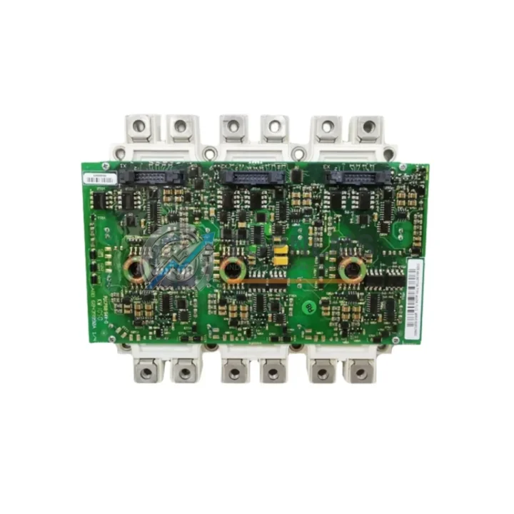
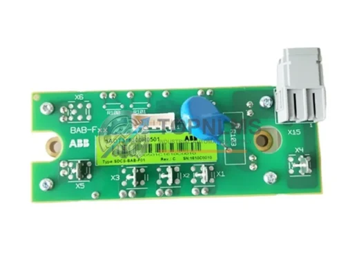
The ABB AGDR-61C (also referenced as FS450R17KE3 / part number 64783831) is a high-power IGBT Gate Driver Assembly engineered for the ABB ACS800 series of industrial AC drives. As ACS800 installations age and original gate driver boards reach end-of-life or become increasingly difficult to source, plant engineers and procurement teams face mounting pressure to restore drive functionality with minimal production downtime. This listing provides a verified, tested replacement unit that supports a smooth, low-risk migration from a failed or degraded gate driver to a fully operational drive system — without requiring a full drive replacement or costly rewiring.
The AGDR-61C gate driver board interfaces directly with the IGBT power module stack inside the ACS800 drive cabinet. Its primary function is to translate low-voltage control signals from the drive’s main control board (such as the RMIO-11C or RMIO-02C) into the precise gate pulses required to switch the IGBT modules at the correct timing, voltage, and current levels. A failed or degraded AGDR-61C typically manifests as overcurrent trips, IGBT fault codes (e.g., FF-52, FF-53), erratic motor behavior, or complete drive shutdown. Replacing the gate driver board is often the most cost-effective corrective action before considering full inverter section replacement.
This replacement unit is compatible with ACS800 drive frames that originally use the FS450R17KE3 IGBT power module (Infineon 1700V / 450A). The gate driver board is pre-matched to the switching characteristics of this module, ensuring correct dead-time, gate resistance, and desaturation protection settings are maintained. No firmware modification or parameter re-entry is required on the drive’s control board after replacement — the ACS800’s existing drive configuration, motor parameters, and fieldbus settings stored in the RMIO board or CDP312R control panel remain intact.
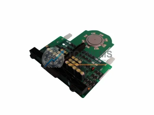
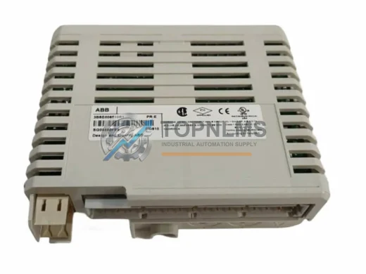
During the retrofit process, engineers typically work alongside several related ACS800 components. The AINT-02C or AINT-14C inverter interface board connects the RMIO control board to the gate driver layer and should be inspected for damage when the AGDR-61C is replaced. The APOW-01C auxiliary power supply board provides the isolated gate driver supply voltages; a failing APOW-01C can cause secondary AGDR-61C failures and should be tested in parallel. In multi-drive or common DC bus configurations, the ARBI-xx brake chopper module and ACSM1 or ACS850 drive units sharing the same DC bus should be verified for correct voltage balance after the gate driver swap.
For installations where the ACS800 is controlled via PROFIBUS-DP using an RPBA-01 adapter, or via Modbus RTU through an RMBA-01 module, no communication reconfiguration is needed following gate driver replacement. The fieldbus node address, baud rate, and process data mapping remain stored in the adapter module and are unaffected by the gate driver board swap. Similarly, if the drive uses an RTAC-01 pulse encoder interface for closed-loop speed control, encoder feedback parameters and scaling factors do not require re-entry.
Physical installation of the replacement AGDR-61C follows the original ABB service manual procedure. The board mounts directly to the IGBT module using the existing standoff hardware. Gate and emitter connections are made via the original ribbon cable or discrete wire harness depending on the drive frame size. Torque specifications for the IGBT module gate terminal screws must be observed precisely to avoid intermittent contact, which can cause nuisance trips or re-failure of the gate driver. The desaturation (desat) feedback circuit between the IGBT module and the gate driver board should be verified with a continuity check before powering up the drive.
After installation, the recommended commissioning sequence includes a DC bus pre-charge check, an insulation resistance test on the motor cable, and a no-load run at reduced speed before returning the drive to full production load. ACS800 drives with the DTC (Direct Torque Control) algorithm will automatically re-identify motor parameters if an ID run is triggered, though this is generally not required after a gate driver replacement unless the motor or cable has also been changed.
For facilities managing a fleet of ACS800 drives, maintaining a spare AGDR-61C / FS450R17KE3 / 64783831 gate driver assembly in the storeroom is a recognized best practice to minimize mean time to repair (MTTR). A single unplanned drive outage in a continuous process environment can cost multiples of the spare part value in lost production. This unit ships fully tested, with all gate driver channels verified under load simulation, and is packaged in anti-static ESD shielding suitable for long-term storage.
Compatibility Comparison Table
| Parameter |
Original / Legacy |
This Replacement Unit |
| Part Number |
ABB 64783831 (OEM) |
AGDR-61C / FS450R17KE3 / 64783831 |
| Compatible Drive Series |
ABB ACS800 (all frames using FS450R17KE3 IGBT) |
ABB ACS800 — direct drop-in replacement |
| IGBT Module Compatibility |
Infineon FS450R17KE3 (1700V / 450A) |
Infineon FS450R17KE3 — pre-matched gate parameters |
| Control Board Interface |
RMIO-11C / RMIO-02C via AINT interface board |
Fully compatible — no signal re-mapping required |
| Gate Drive Supply |
Isolated ±15V from APOW-01C auxiliary supply |
Same supply rail — no power wiring changes |
| Fieldbus Compatibility |
PROFIBUS (RPBA-01), Modbus (RMBA-01), DeviceNet |
No fieldbus reconfiguration required |
| Mounting / Form Factor |
Original ABB ACS800 gate driver PCB footprint |
Identical PCB footprint — original hardware reused |
| Installation Requirement |
Requires drive de-energization and DC bus discharge |
Same procedure — no additional tooling required |
| Parameter Re-entry |
Not required after gate driver swap |
Not required — RMIO retains all drive parameters |
| Warranty |
OEM warranty (typically expired on legacy units) |
12-Month Warranty from TOPNLMS |
Seamless Upgrade Solutions
A successful ACS800 gate driver replacement rarely involves the AGDR-61C in isolation. In practice, the following components are commonly inspected, tested, or replaced as part of the same service event to ensure long-term drive reliability:
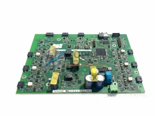
The APOW-01C Auxiliary Power Supply is the first component to verify. It provides the isolated gate driver supply rails and is a common root cause of repeated AGDR-61C failures. If the APOW-01C output voltages are out of tolerance, a new gate driver board will fail prematurely. The AINT-02C Inverter Interface Board sits between the RMIO control board and the gate driver layer; damaged fiber optic connectors or cracked solder joints on the AINT board can cause intermittent gate pulses that mimic a gate driver fault. The RMIO-11C Main Control Board stores all drive parameters and fieldbus configuration — it should be backed up using the CDP312R DriveWindow panel or ABB DriveWindow software before any service work begins.
In ACS800 units with active front-end (AFE) rectifiers, the AGDR-81C gate driver for the supply unit section may also require inspection, as supply-side IGBT faults can be misdiagnosed as inverter-side gate driver failures. For drives using encoder feedback, the RTAC-01 Pulse Encoder Interface Module should be verified for correct 5V or 24V encoder supply output after the drive is re-energized. Finally, if the drive cabinet uses a NINT-41C or NINT-02C inverter control interface in a multi-drive configuration, the fiber optic links between the control board and gate driver boards should be cleaned and inspected as part of the same maintenance window.
Retrofit Guidance FAQ
Q: Do I need to re-enter drive parameters after replacing the AGDR-61C?
A: No. Drive parameters, motor data, and fieldbus settings are stored on the RMIO control board, not the gate driver board. Replacing the AGDR-61C does not affect stored parameters. However, it is best practice to back up parameters to the CDP312R panel or DriveWindow software before beginning any service work.
Q: Can I replace the AGDR-61C without replacing the FS450R17KE3 IGBT module?
A: Yes, provided the IGBT module passes a static gate-emitter and collector-emitter resistance check. If the IGBT module shows signs of internal short circuit or open gate, both the IGBT module and gate driver board should be replaced together to avoid re-failure.
Q: Is the replacement AGDR-61C compatible with all ACS800 frame sizes?
A: The AGDR-61C / FS450R17KE3 combination is specific to ACS800 frames that use the Infineon FS450R17KE3 1700V/450A IGBT module. Please verify your drive’s frame size and IGBT module type against the ABB ACS800 hardware manual before ordering.
Q: What communication protocols are supported after replacement?
A: All ACS800 fieldbus protocols — including PROFIBUS-DP (RPBA-01), Modbus RTU (RMBA-01), DeviceNet (RDNA-01), and CANopen (RCAN-01) — are unaffected by gate driver replacement. Protocol configuration is stored in the respective adapter module and the RMIO board.
Q: How much physical space is required for the replacement?
A: The replacement AGDR-61C uses the identical PCB footprint and mounting hole pattern as the original. No cabinet modifications, bracket changes, or cable extensions are required. The existing gate and emitter wiring harness is reused.
Q: What is the recommended commissioning procedure after installation?
A: (1) Verify DC bus is fully discharged before installation. (2) Install AGDR-61C and reconnect all gate/emitter and fiber optic connections. (3) Apply control power and verify APOW-01C supply rail voltages. (4) Perform a no-load test run at 10–20% speed. (5) Verify drive current and torque readings before returning to full production load.
Warranty Assurance
Every AGDR-61C / FS450R17KE3 / 64783831 unit shipped by TOPNLMS is covered by a 12-month warranty from the date of delivery. Prior to shipment, each unit undergoes a multi-stage outgoing quality inspection that includes visual inspection for PCB damage, component-level verification of gate driver output stages, isolation resistance testing of the gate supply circuits, and a functional test under simulated load conditions. Units that do not pass all inspection stages are not shipped.
In the event of a warranty claim, TOPNLMS provides a replacement unit or full refund based on the customer’s preference and the outcome of the return inspection. Warranty claims are processed within 3 business days of receiving the returned unit. Customers are encouraged to contact our technical team before initiating a return, as many reported faults can be resolved through remote diagnostic support without requiring a physical return.
TOPNLMS maintains stock of AGDR-61C and related ACS800 spare parts to support rapid order fulfillment. Standard orders are dispatched within 1–3 business days from our Xiamen warehouse. Express international shipping options are available for urgent breakdown situations. All units are shipped in anti-static ESD packaging with appropriate cushioning for international freight.
For procurement teams managing approved vendor lists (AVL) or requiring documentation for incoming inspection, TOPNLMS can provide test reports, packing lists, and commercial invoices upon request. Volume pricing is available for storeroom replenishment orders of 3 or more units.
© 2026 TOPNLMS. All rights reserved.
Original Source: https://topnlms.com
Contact: [email protected] | +86 18359293191