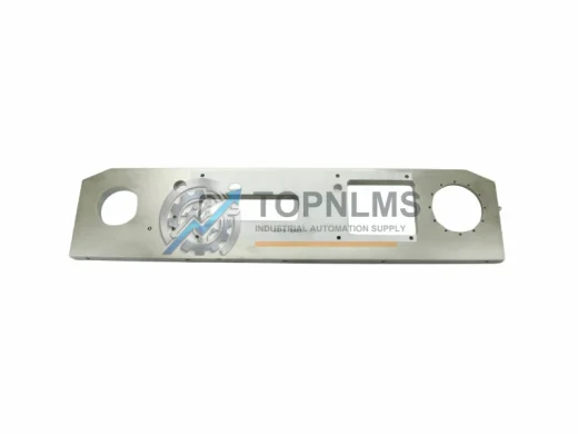
Product Overview
Applied Materials 0050-41494 Original Industrial Spare CLEAN LINE Compatible: System Stability and Industrial Spare Parts Maintenance Value
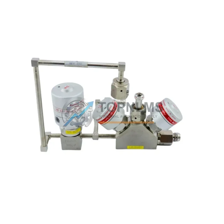
The Applied Materials 0050-41494 is an original normally-closed (N.C.) pneumatic valve assembly engineered for precision gas and fluid control within semiconductor fabrication and advanced industrial process equipment. Operating at a rated pressure range of 0.39–0.59 MPa and cross-referenced under legacy part numbers 543573 and 0021-21779, this valve is a critical flow-control component within the CLEAN LINE series platform. Maintaining verified stock of this valve directly reduces unplanned downtime risk in CVD, PVD, etch, and CMP tool environments where process gas isolation is non-negotiable.
For maintenance engineers and procurement teams managing Applied Materials tool fleets, sourcing a verified original spare for the 0050-41494 is a foundational step in any preventive maintenance (PM) program. The valve’s N.C. fail-safe design ensures that in the event of pneumatic supply loss, the process line defaults to a closed, safe state — a critical safety and process-integrity feature that must be preserved with like-for-like original replacement parts. Reactive procurement of this component during an unplanned outage typically introduces a 3–7 business day lead-time exposure; stocking even a single unit on-site eliminates that risk entirely and protects wafer throughput and tool availability metrics.
Critical Technical Specs
| Parameter |
Specification |
| Part Number |
0050-41494 |
| Cross Reference |
543573 / 0021-21779 |
| Valve Type |
Normally Closed (N.C.) Pneumatic Valve Assembly |
| Series |
CLEAN LINE |
| Operating Pressure |
0.39 – 0.59 MPa |
| Actuation |
Pneumatic (air-operated) |
| Fail-Safe Mode |
Normally Closed — closes on loss of pneumatic supply |
| Application |
Semiconductor process equipment: CVD, PVD, Etch, CMP tools |
| Compatibility |
Applied Materials CLEAN LINE platform; replaces 543573 and 0021-21779 |
| Installation |
Direct drop-in replacement; no modification required for standard configurations |
| Weight |
Approx. 2,600 g |
| Origin |
United States |
| Condition |
Original / New Surplus / Functionally Tested |
| Maintenance Interval |
Per OEM PM schedule or every 12–18 months under continuous operation |
| Warranty |
12 Months — covers manufacturing defects and functional failure under rated conditions |
Preventive Maintenance Strategy
A scheduled PM interval for the 0050-41494 valve should be integrated into the broader tool qualification and chamber maintenance cycle. When replacing or inspecting this valve, maintenance teams should simultaneously audit the surrounding pneumatic and electrical subsystems to maximize uptime and avoid repeat call-outs — a single coordinated shutdown is always more cost-effective than multiple reactive interventions.
Begin with the pneumatic supply line: verify the integrity of the pneumatic tubing and push-in fittings feeding the valve manifold. Micro-leaks in the supply circuit cause erratic valve actuation and false process alarms that are difficult to trace without a systematic pressure-decay test. Next, inspect the solenoid pilot valve — typically a 24 VDC unit mounted on the valve body or manifold block — as solenoid coil degradation is a well-documented co-failure mode with aging pneumatic valves in high-cycle semiconductor environments. Coil resistance should be measured and compared against the OEM specification; a reading outside tolerance is grounds for immediate replacement before the next PM window.
The digital output (DO) I/O module driving the solenoid signal should be verified for correct output voltage and response time. A degraded output channel on the I/O card can mask a valve fault as a process anomaly, leading to misdiagnosis and unnecessary valve replacements. While the control cabinet is open, check the 24 VDC power supply module supplying the solenoid circuit — voltage sag under load is a frequent root cause of intermittent valve response in multi-axis pneumatic systems, and a power supply operating near its rated capacity should be flagged for proactive replacement.
For tools using a pneumatic manifold block to gang multiple valves, inspect the manifold body for hairline cracks, O-ring extrusion, and port contamination. A single degraded manifold can compromise the performance of all valves in the assembly simultaneously. Alongside the manifold, verify the condition of the upstream filter-regulator unit — contaminated or under-regulated supply pressure is the leading cause of premature valve seat wear and is frequently overlooked during single-component replacements.
In the electrical cabinet, inspect the terminal blocks and wiring harness connecting the solenoid to the I/O card. Loose terminations cause intermittent faults that are difficult to reproduce during static testing but manifest as process interruptions during thermal cycling. If the tool uses a PLC or DCS controller for valve sequencing — such as an Applied Materials proprietary controller or a third-party Siemens S7 or Allen-Bradley ControlLogix platform — confirm that the ladder logic or function block for the 0050-41494 output channel has not been modified during recent software updates. Configuration drift is a documented source of valve-related process deviations in facilities with active software change management programs.
For tools approaching end-of-life or operating beyond their original design cycle, consider a full pneumatic valve kit replacement covering all N.C. and N.O. valves in the process module simultaneously. Staggered valve failures in aging CLEAN LINE systems are a well-documented maintenance burden; a coordinated replacement during a planned shutdown — including the 0050-41494 alongside companion valves, solenoid assemblies, pressure sensors, and signal isolators in the same pneumatic circuit — is significantly more cost-effective than reactive single-valve replacements during unplanned downtime events.
Strategic Replacement Solutions
The 0050-41494 is the current Applied Materials part number superseding legacy references 543573 and 0021-21779, which appear in older CLEAN LINE tool bills of materials (BOMs) and may no longer be available through OEM distribution channels. Sourcing the current 0050-41494 revision ensures full mechanical and functional compatibility without requiring tool re-qualification in most standard configurations, preserving the original process recipe and reducing the engineering overhead associated with introducing a non-OEM substitute.
For facilities managing a mixed fleet of Applied Materials tools across multiple technology nodes, standardizing on the 0050-41494 as the single stocked SKU for N.C. pneumatic valve replacements across compatible CLEAN LINE platforms simplifies inventory management and reduces the risk of incorrect part installation during high-pressure maintenance windows. A recommended minimum stock level of 2–3 units per active tool cluster provides adequate buffer for both scheduled PM replacements and unplanned failures without excessive carrying cost — a standard practice in facilities operating under aggressive tool availability targets.
When transitioning from older 543573-series valves, verify the pneumatic port thread specification and body mounting pattern against the tool’s current mechanical drawing revision. In the majority of documented field replacements, the 0050-41494 installs without modification. However, tools that have undergone field engineering changes (FECs) may require a brief mechanical verification before installation. Our technical team can assist with cross-reference confirmation prior to order placement upon request.
Stocking this part as a strategic spare — rather than ordering reactively — reduces mean time to repair (MTTR) for pneumatic valve faults from a typical 3–7 business day lead-time scenario to a same-shift replacement, directly protecting wafer throughput, tool availability metrics, and production schedule commitments.
Support FAQ
Q1: Is the 0050-41494 a direct drop-in replacement for 543573 and 0021-21779?
Yes. The 0050-41494 is the current Applied Materials part number superseding 543573 and 0021-21779 within the CLEAN LINE series. In standard tool configurations, it installs as a direct mechanical and functional replacement. We recommend verifying the port orientation and mounting pattern against your tool’s current BOM revision before installation if the tool has undergone field engineering changes (FECs).
Q2: What is the recommended stock quantity for a facility running multiple CLEAN LINE tools?
For facilities operating 3 or more CLEAN LINE process modules, we recommend maintaining a minimum of 2–3 units of the 0050-41494 in local inventory. This buffer supports both scheduled PM cycles and unplanned failures without incurring excessive carrying cost, and eliminates the 3–7 business day lead-time exposure associated with reactive procurement during active production.
Q3: How is each unit tested and verified before shipment?
Each 0050-41494 unit undergoes functional actuation testing and pneumatic leak verification prior to shipment. Units are inspected for valve seat integrity, solenoid coil continuity, and body seal condition. A test report is available upon request. All units are shipped in protective, moisture-resistant packaging suitable for precision industrial spare parts handling.
Q4: What does the 12-month warranty cover?
The 12-month warranty covers manufacturing defects and functional failure under normal operating conditions within the specified pressure range (0.39–0.59 MPa). Warranty claims are processed within 5 business days of receipt of the returned unit. Replacement or full refund is provided based on failure analysis. The warranty does not cover damage resulting from installation outside the specified operating parameters, physical mishandling, or use in applications outside the intended CLEAN LINE platform environment.
© 2026 TOPNLMS. All rights reserved.
Original Source: https://topnlms.com
Contact: [email protected] | +86 18359293191