
A machine that reports speed reliably once running can still have an inadequate speed signal during starting. For maintenance teams working with a Woodward governor and a passive magnetic pickup, that distinction should be investigated before the control is condemned. A good running-speed indication does not establish what the input saw during the first seconds of cranking.
The practical question is whether the control receives a suitable signal throughout the required operating sequence. Answer it with the exact equipment manual and measured evidence. Do not turn a general magnetic-pickup principle into a universal voltage threshold, air-gap setting or terminal assignment for every Woodward control.
Why low speed changes the evidence
Woodward’s Governing Fundamentals and Power Management, manual 26260 explains the passive magnetic pickup and the factors affecting its output. These include gear surface speed, the pickup-to-gear gap, physical geometry and connected impedance. A measurement made at normal operating speed therefore does not automatically represent the signal available at cranking.
The manual provides a useful foundation, not the acceptance specification for every installed device. Obtain the instructions for the actual control and pickup combination. Establish its required signal characteristics, wiring and test conditions before collecting numbers that may otherwise be impossible to interpret.
Also verify the sensing technology. A passive magnetic pickup is not interchangeable with every powered proximity sensor or other speed source. The presence of a speed value on the operator display does not identify the electrical interface behind it.
Preserve the symptom before replacing the control
Record when the speed indication becomes credible: immediately on cranking, only after acceleration, intermittently, or not at all. Keep that observation separate from conclusions about the cause. Include relevant alarms, the operating state and the evidence available from the approved diagnostic tools.
If a team is considering a Woodward 9905-068 control inquiry, the full installed label and application documentation should accompany it. Do not assume that the commercial series description on a listing supplies the input specification, terminal numbers or approved settings for the unit in service.
The same discipline applies to a Woodward 9905-864 PEAK150 reference. These are distinct sourcing references, not a proposed substitution pair. Their appearance in the same discussion does not mean that one can replace the other or that their commissioning procedures are identical.
Measure at the relevant boundary
A signal observed at the sensor and a signal received at the control are not necessarily the same evidence. The cable, connections and input loading are part of the measurement path. The approved diagnostic procedure should identify where a measurement is taken and whether the circuit is connected as required for that test.
Record the instrument, measurement mode, test point and machine state. A number without those details is difficult to compare later. Where waveform assessment is appropriate, it should be performed by qualified personnel using equipment and methods suitable for the circuit. A generic meter reading should not be promoted into proof of every required signal characteristic.
Compare cranking evidence with the applicable specification, then examine how the signal changes as the authorized test sequence progresses. Do not intentionally disable protection, alter fuel admission or bypass a start permissive to obtain a more convenient reading. The machine’s safety and operating procedures remain the controlling requirements.
Mechanical checks need a stopped, secured machine
Inspect the pickup mounting, condition and target arrangement only under the appropriate isolation and mechanical safety controls. Preserve the as-found condition before making adjustments. An observed gap or mounting concern is evidence to evaluate against the equipment documentation, not permission to apply a remembered setting from another engine.
Check records for recent work that could have changed the sensing path. A sensor replacement, cable repair, mechanical overhaul or control exchange can alter the comparison with earlier operating data. Establish what changed and when instead of treating every no-speed symptom as the same failure mode.
If an adjustment is authorized, document its basis and the resulting verification. Keep the original observation available. Without an as-found record, a successful restart may solve the immediate problem while leaving the plant unable to explain why it happened or how to detect recurrence.
Make the spare decision evidence-led
Separate confirmed control defects from unresolved input-path questions. A replacement governor may be necessary, but it should not become a substitute for measuring a weak or interrupted signal. Conversely, a plausible sensor explanation should not prevent a control from receiving an appropriate assessment when the input evidence is sound.
Define the intended recovery package precisely. It may concern the control, a sensor, connection hardware or a separately approved repair. State what is included in the quotation and what the site will retain. Request readable identification evidence and an agreed test scope rather than an unspecified promise that the supplied unit has been checked.
After repair or replacement, verify the approved starting and operating sequence, not just a normal-speed display. Record the results, relevant limitations and the responsible sign-off. Independent overspeed and other protective functions must remain governed by their own approved requirements; a speed indication check is not a complete protection-system test.
Questions that avoid an unnecessary purchase
Does a correct speed reading after startup prove the pickup is healthy?
It proves only the observed behavior in that condition. The signal at cranking may differ. Compare evidence from the required operating states against the actual pickup and control specifications before concluding that the entire sensing path is qualified.
Can we use one minimum voltage for every Woodward governor?
No. Use the applicable manual for the exact control and speed-source arrangement, including its measurement conditions. A threshold copied from another model can produce a false pass or an unnecessary rejection.
Should we reduce the pickup gap until the machine starts?
No. Any mechanical adjustment must follow the manufacturer’s instructions and the site’s isolation procedure. Changing the gap by trial and error can introduce mechanical or electrical problems and does not establish why the original signal was inadequate.
What information helps a supplier assess the control request?
Provide the full label, application reference, condition requirement, quantity and destination. Add a concise account of the symptom and the verified input evidence. Clearly identify what remains uncertain so a quotation is not mistaken for approval of the complete machine configuration.
Contact TOPNLMS with the exact Woodward reference and the evidence already collected for a focused quotation. A measured cranking-speed record helps maintenance distinguish a control requirement from a sensor-path problem and makes the eventual spare decision easier to defend.
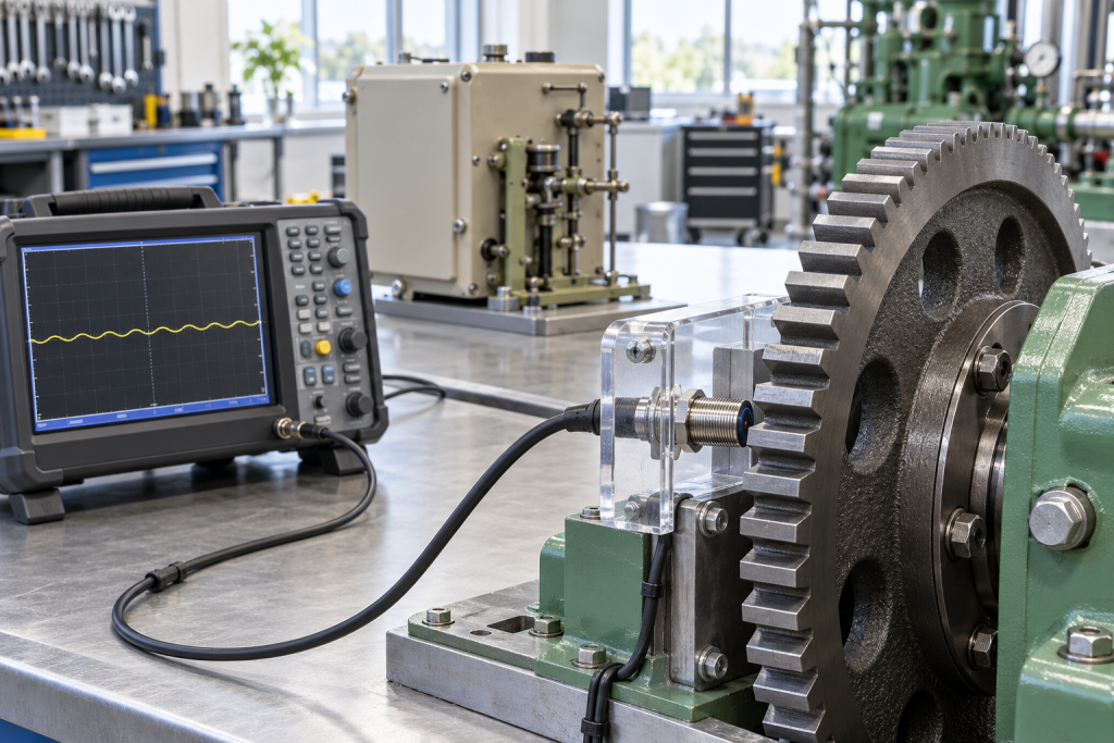
Image: AI-generated editorial illustration, not an exact product photograph or installation reference.
© 2026 TOPNLMS. All rights reserved. Official Website: https://topnlms.com Inquiry: [email protected] | WhatsApp/Tel: +86 18359293191