Siemens
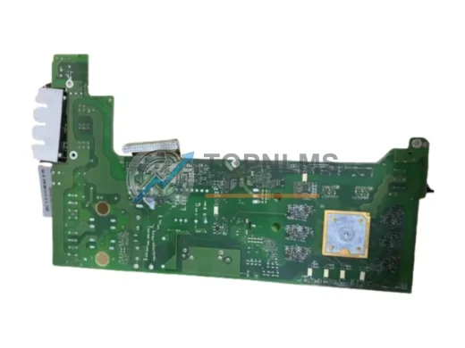
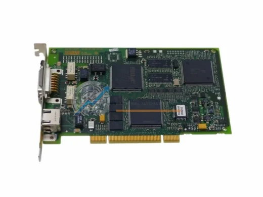
Siemens A5E01161647 Ruggedized CP Communication Module
A5E01161647Siemens A5E01161647 SIMATIC S7 CP communication module. Rugged, EMC-rated, tested. 12-month warranty. In stock at TOPNLMS — fast global shipping.
Request availability, condition, lead time and export shipping details for 6ES7153-2BA01-0XB0.
Send this exact part number, quantity and destination country. TOPNLMS will confirm availability, condition and export lead time before quotation.
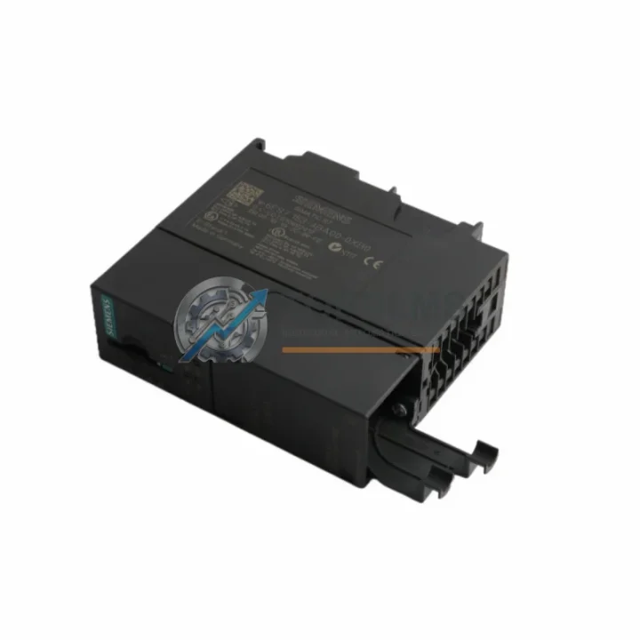
The Siemens 6ES7153-2BA01-0XB0 is the IM 153-2 interface module for the ET 200M distributed I/O station, designed to connect the ET 200M rack to a PROFIBUS DP master — typically a SIMATIC S7-300, S7-400, or compatible third-party PLC controller. As Siemens progressively phases out legacy SIMATIC hardware, many plants operating ET 200M stations with older IM 153-1 or early IM 153-2 variants are now facing end-of-life supply constraints. The 6ES7153-2BA01-0XB0 serves as the direct replacement and upgrade path for those discontinued interface modules, offering full backward compatibility with existing ET 200M racks, signal modules, and PROFIBUS DP wiring infrastructure.
For facilities running SIMATIC S7-300 CPUs — such as the CPU 315-2 DP, CPU 317-2 DP, or CPU 319-3 PN/DP — the IM 153-2 module slots directly into the ET 200M rack without requiring rewiring of the PROFIBUS DP bus connector or reconfiguration of the DP address. The module supports baud rates up to 12 Mbit/s and is fully compatible with STEP 7 V5.x hardware configuration, meaning existing GSD files and hardware configurations can be retained during the swap. This dramatically reduces engineering time and eliminates the need for a full system re-commissioning.
When migrating from an older IM 153-1 (6ES7153-1AA03-0XB0) to the IM 153-2 (6ES7153-2BA01-0XB0), the physical rack, backplane bus, and all installed signal modules — including SM 321 digital input modules, SM 322 digital output modules, SM 331 analog input modules, and SM 332 analog output modules — remain in place. Only the interface module itself is replaced. The PROFIBUS DP address is set via the rotary switch on the module face, matching the address previously assigned in the STEP 7 hardware configuration. No changes to the PLC program or I/O mapping are required, making this one of the lowest-risk hardware replacements in the SIMATIC ecosystem.
For plants operating a distributed control architecture with multiple ET 200M stations across a PROFIBUS DP segment, the 6ES7153-2BA01-0XB0 supports redundancy configurations when paired with a second IM 153-2 module and a Y-Link coupler (6ES7197-1LB00-0XA0). This redundancy capability is critical for high-availability processes in chemical, petrochemical, power generation, and water treatment applications where unplanned downtime carries significant operational cost. The module’s active standby switching ensures seamless failover without interrupting the DP communication cycle.
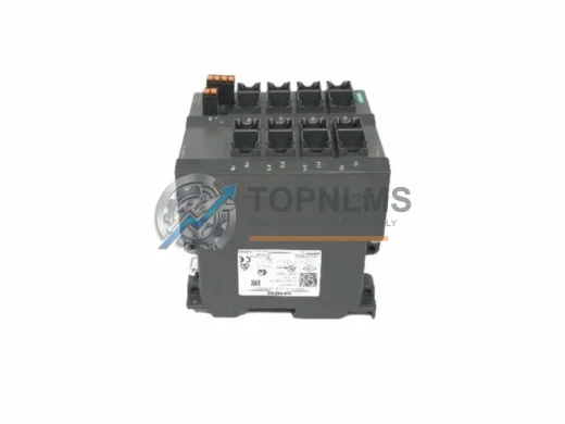
Power supply compatibility is another key consideration during retrofit projects. The ET 200M station is powered by a dedicated PS 307 power supply module (e.g., 6ES7307-1BA01-0AA0 or 6ES7307-1EA00-0AA0), which remains unchanged when replacing the interface module. The 24 VDC backplane supply and the load voltage for output modules are unaffected by the IM swap, ensuring that the electrical installation in the control cabinet requires no modification. This is particularly important in panel-space-constrained installations where re-wiring would require significant downtime and labor.
Communication protocol continuity is fully preserved. The 6ES7153-2BA01-0XB0 uses the standard 9-pin Sub-D PROFIBUS DP connector, compatible with all existing PROFIBUS cables, bus terminators, and repeaters already installed in the field. Plants using PROFIBUS DP/PA segment couplers or DP/PA links to connect HART-enabled field instruments will find that the IM 153-2 replacement has no impact on the PA segment configuration or instrument parameterization. The DP master continues to poll the ET 200M station at the same cycle time, and all process values are transmitted without interruption after the module swap and power cycle.
| Parameter | Legacy: IM 153-1 (6ES7153-1AA03-0XB0) | Replacement: IM 153-2 (6ES7153-2BA01-0XB0) |
|---|---|---|
| Series | ET 200M | ET 200M |
| Interface | PROFIBUS DP (Slave) | PROFIBUS DP (Slave) |
| Max Baud Rate | 12 Mbit/s | 12 Mbit/s |
| Redundancy Support | No | Yes (with Y-Link 6ES7197-1LB00-0XA0) |
| DP Address Setting | Rotary switch | Rotary switch (same method) |
| Rack Compatibility | ET 200M rack (UR1/UR2) | ET 200M rack (UR1/UR2) — direct fit |
| Signal Module Compatibility | SM 321/322/331/332 | SM 321/322/331/332 — fully compatible |
| STEP 7 Configuration | STEP 7 V5.x | STEP 7 V5.x (same GSD, no re-config needed) |
| Power Supply | 24 VDC via backplane | 24 VDC via backplane — unchanged |
| Connector Type | 9-pin Sub-D PROFIBUS | 9-pin Sub-D PROFIBUS — same cable |
| Installation Space | Slot 1 of ET 200M rack | Slot 1 of ET 200M rack — no panel change |
| Replacement Complexity | — | Low — module swap only, no rewiring |
| Warranty | — | 12-Month Warranty (TOPNLMS) |
A successful ET 200M migration involves more than just the interface module. During the replacement process, engineers frequently audit and refresh adjacent components to ensure system reliability for the next operational cycle. The ET 200M rack itself — available in UR1 (4-slot) and UR2 (8-slot) configurations — should be inspected for backplane bus connector wear, particularly in high-vibration environments. If the rack is original to the installation, replacing it alongside the IM 153-2 is a cost-effective decision that eliminates a future single point of failure.
The PS 307 power supply module (6ES7307-1BA01-0AA0 for 2A output or 6ES7307-1EA00-0AA0 for 5A output) is another component commonly refreshed during an IM 153-2 upgrade. Aging power supplies with capacitor degradation can cause intermittent backplane voltage drops that manifest as sporadic DP communication errors — symptoms that are often misdiagnosed as interface module faults. Replacing the PS 307 during the same maintenance window eliminates this diagnostic ambiguity.
For plants that need to reprogram or re-download the STEP 7 hardware configuration after the module swap, a PC adapter USB (6ES7972-0CB20-0XA0) or MPI/PROFIBUS programming cable is required to establish a connection between the engineering workstation and the S7-300 CPU. Having this cable on hand before the maintenance window begins prevents delays caused by last-minute procurement. Similarly, if the CPU’s memory card (6ES7953-8LF31-0AA0 or equivalent) is due for replacement, the IM 153-2 swap is an ideal opportunity to refresh it and ensure the program backup is current.
Signal module integrity should also be verified during the retrofit. SM 321 (6ES7321-1BH02-0AA0) digital input modules and SM 322 (6ES7322-1BH01-0AA0) digital output modules that have been in service for more than ten years may exhibit channel failures or increased leakage current. Replacing suspect signal modules during the same outage window — rather than reactively after restart — significantly reduces the risk of a second unplanned shutdown. Analog modules such as the SM 331 (6ES7331-7KF02-0AB0) and SM 332 (6ES7332-5HF00-0AB0) should have their calibration verified post-restart to confirm that the backplane swap has not introduced any offset errors.
Finally, for installations where the ET 200M station communicates with field instruments via PROFIBUS PA, the DP/PA coupler (6ES7157-0AC83-0XA0) and PA segment termination should be inspected. A clean PROFIBUS PA segment with proper termination and shielding is essential for stable communication after the IM 153-2 replacement, particularly in environments with high electromagnetic interference from variable frequency drives or large motor starters in the same control cabinet.
Q: Do I need to rewire the PROFIBUS DP cable when replacing the IM 153-1 with the 6ES7153-2BA01-0XB0?
No. The 6ES7153-2BA01-0XB0 uses the same 9-pin Sub-D PROFIBUS DP connector as the IM 153-1. The existing cable, bus connector, and termination resistor can be reused without modification. Simply disconnect the bus connector from the old module and reconnect it to the new one.
Q: Will I need to modify my STEP 7 hardware configuration or PLC program?
In most cases, no. If you are replacing an IM 153-2 of the same order number, the hardware configuration is identical and no changes are required. If upgrading from an IM 153-1, you will need to update the hardware configuration in STEP 7 to reflect the new module type and re-download the configuration to the CPU. The I/O addresses and program logic remain unchanged.
Q: Can the 6ES7153-2BA01-0XB0 be used in a redundant configuration?
Yes. When paired with a second IM 153-2 module and a Y-Link coupler (6ES7197-1LB00-0XA0), the ET 200M station supports active redundancy. The Y-Link connects to two independent PROFIBUS DP masters, and the standby IM takes over automatically if the active IM or its DP segment fails. This configuration is supported in STEP 7 with the appropriate hardware configuration settings.
Q: What is the physical installation space requirement?
The IM 153-2 occupies Slot 1 of the ET 200M rack (UR1 or UR2). Its physical dimensions are identical to the IM 153-1, so no panel modification, DIN rail adjustment, or cable duct repositioning is required. The module is secured by the standard rack locking mechanism.
Q: How do I set the PROFIBUS DP address on the new module?
The DP address is set using the two rotary switches on the front face of the module, in the same manner as the IM 153-1. Set the address to match the value configured in your STEP 7 hardware configuration. Valid addresses are 1–125. Ensure the address is set before powering up the station to avoid address conflicts on the DP segment.
Q: What should I check after replacing the module and powering up?
Verify that the BF (Bus Fault) LED on the IM 153-2 is off and the SF (System Fault) LED is off. Check the DP master CPU for any OB86 (rack failure) or OB122 (I/O access error) calls in the diagnostic buffer. Confirm that all signal modules are reporting correctly in the STEP 7 online view. If the BF LED remains on, check the DP address setting, bus termination, and cable continuity.
Every Siemens 6ES7153-2BA01-0XB0 shipped by TOPNLMS is covered by a 12-month warranty from the date of delivery. Prior to shipment, each unit undergoes a functional inspection including visual examination, connector integrity check, and firmware version verification. Units are packaged in anti-static ESD bags with foam cushioning to prevent transit damage, and shipment tracking is provided for all orders.
In the event of a confirmed hardware defect within the warranty period, TOPNLMS provides a replacement unit or full refund at the buyer’s discretion. Our technical support team is available to assist with installation questions, STEP 7 configuration guidance, and compatibility verification before and after purchase. Response time for warranty claims and technical inquiries is within one business day.
We maintain stock of the 6ES7153-2BA01-0XB0 and related ET 200M components to support urgent replacement requirements. Express shipping options are available for time-critical plant maintenance situations. All units are sourced through verified supply channels and are accompanied by documentation upon request.
For procurement inquiries, bulk pricing, or technical pre-sales support, contact our team directly.
Siemens A5E01161647 SIMATIC S7 CP communication module. Rugged, EMC-rated, tested. 12-month warranty. In stock at TOPNLMS — fast global shipping.
Buy Siemens 6GK5216-0BA00-2AA3 SCALANCE X216 original industrial spare. 16-port managed Ethernet switch, PROFINET compatible, 12-month warranty, fast shipping.
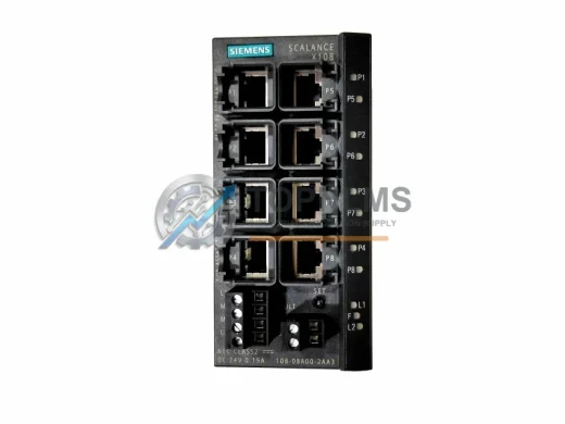
Original Siemens 6GK5108-0BA00-2AA3 SCALANCE X108 8-port unmanaged industrial Ethernet switch. Compatible replacement, 12-month warranty, fast worldwide shipping.
SIEMENS 6GK1161-3AA01 CP1613 SIMATIC NET Ethernet PCI card. Original industrial spare, S7-compatible, 12-month warranty, tested before shipment. Fast worldwide delivery.
Click Quote This Model and the Part Number field will auto-fill with 6ES7153-2BA01-0XB0.