Parker Hannifin
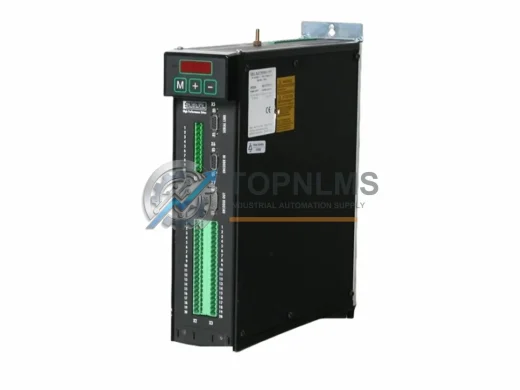
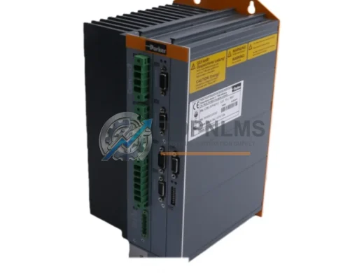
Parker HPD5N Compumotor Digital Servo Drive Replacement
HPD5NParker HPD5N Compumotor digital servo drive replacement. Compatible upgrade for legacy Compumotor series. 12-month warranty, fast shipping. SKU: HPD5N.
Request availability, condition, lead time and export shipping details for 150-A135NBDB.
Send this exact part number, quantity and destination country. TOPNLMS will confirm availability, condition and export lead time before quotation.
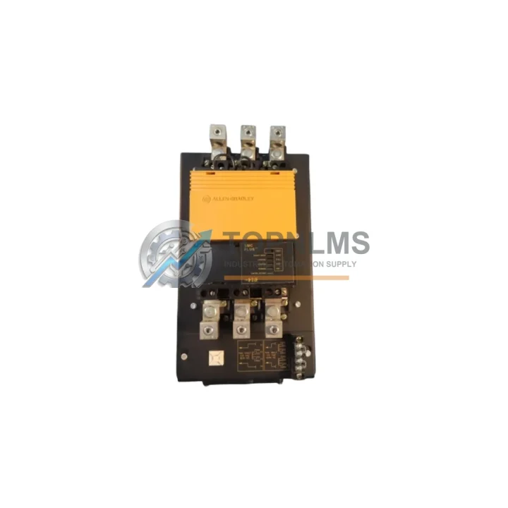
The Parker 150-A135NBDB is a 135A SCR regenerative DC speed controller from Parker Hannifin’s proven 150 Series drive platform. As legacy DC drive systems age and original equipment reaches end-of-life, facilities running Parker SSD, Eurotherm, or earlier 590 Series DC drives face increasing pressure to source reliable replacement units or plan a structured migration path. The 150-A135NBDB addresses both needs: it serves as a direct drop-in replacement for worn or failed 150 Series units and provides a compatible upgrade bridge for engineers transitioning from older regenerative drive architectures.
This unit is rated for 135A continuous output current, designed for four-quadrant regenerative operation, and supports armature voltage feedback as well as tachogenerator feedback configurations. Whether your existing installation uses analog speed reference signals (0–10 VDC or ±10 VDC), potentiometer control, or hardwired enable/inhibit logic, the 150-A135NBDB accommodates these interfaces without requiring extensive rewiring or PLC program modification.
| Parameter | Legacy / Outgoing Model | Parker 150-A135NBDB | Retrofit Notes |
|---|---|---|---|
| Drive Type | SCR Regenerative DC Drive | SCR Regenerative DC Drive | Direct category match |
| Output Current | Varies (90A–150A legacy range) | 135A continuous | Verify motor nameplate FLA ≤ 135A |
| Supply Voltage | 230/460 VAC 3-phase | 230/460 VAC 3-phase | No transformer change required |
| Speed Feedback | Armature voltage / Tacho | Armature voltage / Tacho | Existing feedback wiring reusable |
| Speed Reference Input | 0–10 VDC / ±10 VDC analog | 0–10 VDC / ±10 VDC analog | PLC AO wiring unchanged |
| Enable / Inhibit Logic | Hardwired relay / DI | Hardwired relay / DI | Terminal mapping may require verification |
| Mounting Format | Panel-mount chassis | Panel-mount chassis | Check DIN rail or bolt-hole pattern |
| Communication Protocol | Analog / hardwired (no fieldbus) | Analog / hardwired | Optional SSD serial comms adapter available |
| Enclosure / IP Rating | Open chassis (IP00) | Open chassis (IP00) | Install in existing control cabinet |
| Warranty | OEM warranty expired | 12-Month Warranty | Covered from date of shipment |
A successful migration from a failed or obsolete DC drive system involves more than swapping the drive chassis. When replacing the 150-A135NBDB or upgrading from an earlier Parker SSD 590 Series DC drive, engineers typically need to audit the full drive stack within the control cabinet. The armature and field wiring connected to the existing DC motor must be verified against the 150-A135NBDB terminal layout — in most cases, the A+/A− armature terminals and F+/F− field terminals follow the same convention as earlier 150 Series and 590P units, allowing the existing cable runs to remain intact.
For installations where the original drive communicated with a Siemens S7-300 or Allen-Bradley SLC 500 PLC via analog output cards, the 150-A135NBDB accepts the same 0–10 VDC speed reference signal, meaning the PLC program’s analog output scaling block requires no modification. If the legacy system used a Parker SSD 5703 or 5705 communications interface for serial speed reference, a compatible serial adapter can be retained or replaced with a direct analog reference to simplify the architecture.
In multi-drive systems — for example, a winder/unwinder line using two or more regenerative DC drives — the 150-A135NBDB can be installed alongside existing 150 Series units already in the cabinet, sharing the same AC supply bus and control transformer. The Parker 150-A075NBDB (75A variant) and 150-A180NBDB (180A variant) are common companions in such configurations, covering different motor ratings within the same mechanical and electrical footprint. The field supply section, typically provided by a Parker 150-FBD field controller or a separate field excitation module, remains compatible and does not require replacement during a like-for-like drive swap.
Where the control cabinet includes a Parker HMI operator station or a third-party panel-mount HMI connected via RS-232 or RS-485 for speed monitoring and fault display, the existing communication wiring and HMI program logic can be preserved. The 150-A135NBDB’s diagnostic LED indicators and fault relay output are consistent with the 150 Series platform, so SCADA or DCS alarm inputs wired to the drive’s fault relay will continue to function without rewiring.
For sites upgrading from a completely obsolete drive where the original programming cable and parameter backup are unavailable, a Parker SSD programming cable (compatible with the 6901 or 6911 keypad interface) allows technicians to connect a laptop running DSE Lite or Drive System Explorer software to read, configure, and save drive parameters before commissioning. This is particularly important when the replacement drive is being pre-configured in a workshop environment prior to site installation, reducing on-site commissioning time and minimizing production downtime.
Signal isolation is another consideration in retrofit projects. Where the PLC analog output shares a common ground with other field instruments, a DIN-rail-mounted signal isolator or loop isolator inserted between the PLC AO card and the drive speed reference input eliminates ground loop interference that can cause speed instability. Similarly, if the installation includes proximity sensors or encoder feedback routed through the same cable tray as the drive’s power cables, shielded signal cables with proper grounding at one end are recommended to maintain speed regulation accuracy.
Q: Can I reuse the existing armature and field wiring from the old drive?
A: In most cases, yes. The 150-A135NBDB uses the same A+/A−/F+/F− terminal convention as earlier 150 Series units. Verify wire gauge is rated for 135A on the armature circuit. Inspect insulation condition before re-terminating.
Q: Do I need to modify my PLC program after replacing the drive?
A: If your PLC sends a 0–10 VDC or ±10 VDC analog speed reference, no program changes are required. The drive accepts the same signal range. Only re-verify the analog output scaling if the motor’s base speed or maximum speed setpoint differs from the original configuration.
Q: What communication protocols does the 150-A135NBDB support?
A: The base unit uses analog speed reference and hardwired digital I/O (enable, inhibit, fault relay). Optional serial communication via the SSD serial interface supports RS-232/RS-485 for parameter access and monitoring. It does not natively support Profibus, DeviceNet, or EtherNet/IP without an external gateway.
Q: Will the drive fit in the existing control cabinet without modification?
A: The 150 Series uses a panel-mount open chassis format. Verify the cabinet has adequate clearance for the unit’s dimensions and sufficient airflow for cooling. The 135A chassis requires adequate ventilation — confirm the existing cabinet fan or forced-air cooling arrangement meets the drive’s thermal requirements.
Q: How do I back up and restore drive parameters during replacement?
A: Use a Parker SSD programming cable connected to the drive’s keypad port with DSE Lite software to upload the parameter set from the outgoing drive (if still functional) and download it to the replacement unit. If the original drive is non-functional, parameters must be re-entered manually from the original commissioning sheet or re-tuned on-site.
Q: What is the lead time and shipping arrangement?
A: Units are inspected, tested, and ready to ship from Xiamen. Standard international express delivery (DHL/FedEx) typically reaches most destinations within 3–7 business days. Expedited options are available for urgent breakdown situations. All units ship with a test report and packing list.
Every Parker 150-A135NBDB unit supplied by TOPNLMS is covered by a 12-month warranty from the date of shipment. Prior to dispatch, each unit undergoes a pre-shipment functional test covering power-on verification, output current check, speed reference response, and fault relay operation. Units that do not pass inspection are not shipped.
In the event of a warranty claim, TOPNLMS provides replacement support with priority processing. Our technical team is available to assist with fault diagnosis, parameter verification, and installation guidance via email or phone. We understand that drive failures in industrial environments carry significant production impact, and our after-sales response is structured to minimize your downtime.
Procurement teams can request a formal quotation, proforma invoice, and product test certificate. We support T/T bank transfer, and documentation for customs clearance (commercial invoice, packing list, certificate of origin) is provided with every shipment. Bulk orders and long-term supply agreements are welcome — contact us to discuss pricing and stock reservation arrangements.
For technical pre-sales enquiries, compatibility verification, or urgent replacement sourcing, contact our team directly:
📧 [email protected] | 📞 +86 18359293191
Parker HPD5N Compumotor digital servo drive replacement. Compatible upgrade for legacy Compumotor series. 12-month warranty, fast shipping. SKU: HPD5N.
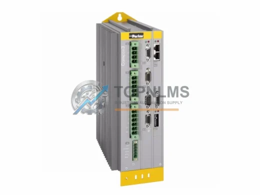
Parker C3S038V4F10I20T40M00 Compax3 single-axis servo drive, EtherCAT, onboard PLC. Original spare, 12-month warranty. Fast shipping for industrial replacement.
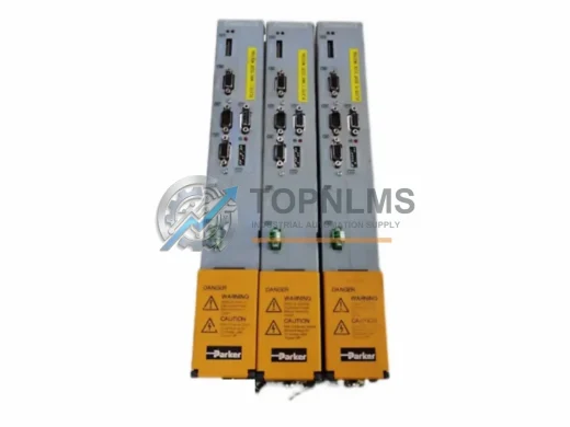
Parker C3M050D6F11I20F30M00S0 Compax3 servo drive module. PROFIBUS-DP, resolver feedback. Rugged, reliable, 12-month warranty. Fast shipping from stock.
Parker C3S150V4 F10 I20 T40 M11 Compax3 single-axis servo drive. Original industrial spare, 150A, multi-option. Fast shipping, 12-month warranty. topnlms.com
Click Quote This Model and the Part Number field will auto-fill with 150-A135NBDB.