FUJI Electric
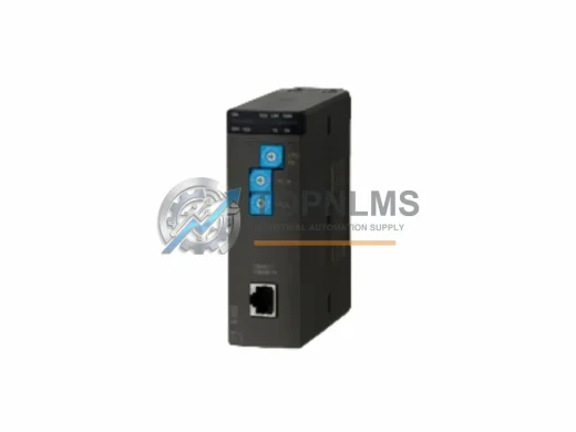
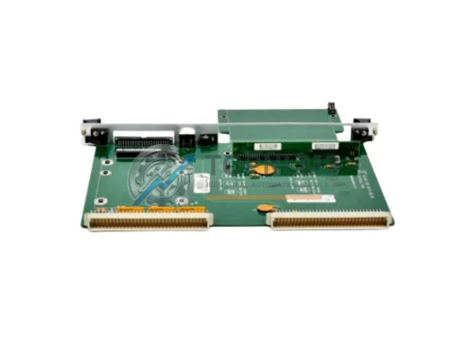
FUJI NP1L-FL3 Ruggedized FL-net Module for Harsh Environments
NP1L-FL3FUJI NP1L-FL3 ruggedized FL-net communication module for MICREX-NX PLC. In stock, tested, 12-month warranty. Built for harsh industrial environments.
Request availability, condition, lead time and export shipping details for NP1L-RJ1.
Send this exact part number, quantity and destination country. TOPNLMS will confirm availability, condition and export lead time before quotation.
The FUJI NP1L-RJ1 is the factory-specified RJ-Interface communication module for the FUJI Electric NP1L series programmable logic controller platform. As industrial facilities worldwide face the challenge of maintaining aging FUJI NP1L-based control systems — many of which were commissioned in the 1990s and early 2000s — the NP1L-RJ1 remains a critical spare and upgrade component for engineers seeking to extend system life, reduce unplanned downtime, and preserve existing wiring infrastructure without a full controller replacement.
Whether your facility is replacing a failed communication module, upgrading from an earlier NP1L-RJ variant, or migrating a legacy FUJI SPB or MICREX-SX architecture toward a more maintainable NP1L-based topology, the NP1L-RJ1 provides a direct, drop-in solution that preserves your existing RJ-45 network wiring, ladder logic program structure, and control cabinet layout. This guide covers everything your engineering and procurement team needs to evaluate, source, and deploy the NP1L-RJ1 with confidence.
| Parameter | Legacy / Replaced Module | FUJI NP1L-RJ1 (This Unit) |
|---|---|---|
| Compatible PLC Series | FUJI NP1L (earlier RJ variants), FUJI SPB series | FUJI NP1L Series (all sub-variants) |
| Communication Interface | RS-232C / RS-485 serial (older modules) | RJ-45 (Ethernet-compatible physical layer) |
| Protocol Support | Proprietary FUJI serial link, Modbus RTU | FUJI RJ-Link, compatible with NP1L network topology |
| Mounting / Form Factor | NP1L backplane slot (left-side expansion) | NP1L backplane slot — direct plug-in replacement |
| Power Supply Requirement | Drawn from NP1L CPU backplane (5 VDC internal bus) | Drawn from NP1L CPU backplane (5 VDC internal bus) |
| Wiring Compatibility | DB9 / terminal block (serial variants) | RJ-45 patch cable — no rewiring required for RJ-equipped panels |
| Program Re-upload Required | Yes (if changing protocol type) | No (if replacing same NP1L-RJ1 model — direct swap) |
| Cabinet Space Impact | Same slot footprint | Same slot footprint — no DIN rail or panel modification needed |
| Replacement Recommendation | Discontinue serial-only modules; migrate to RJ interface | Recommended drop-in for all NP1L RJ-interface positions |
| Warranty | N/A (legacy / end-of-life) | 12-Month Warranty — covered from date of shipment |
A successful NP1L-RJ1 migration rarely involves a single module in isolation. In practice, field engineers replacing or upgrading the RJ-Interface communication module on an NP1L system will encounter a broader set of components that must be evaluated for compatibility, condition, and availability.
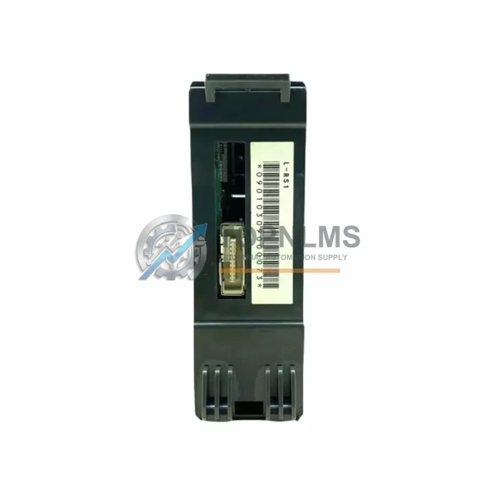
The NP1L-RJ1 slots directly into the NP1L CPU backplane alongside the main CPU module — typically an NP1L-RS1 or NP1L-RS2 CPU unit — which handles the core ladder logic execution. If the CPU itself is approaching end-of-life or showing intermittent faults, it is advisable to source a replacement CPU module at the same time to avoid a second maintenance window. The NP1L backplane and rack assembly are shared resources; verifying that the NP1L expansion backplane connectors are free of corrosion or mechanical damage before inserting the new RJ1 module is a standard pre-installation step.
On the I/O side, NP1L systems typically integrate NP1X digital input modules and NP1Y digital output modules for discrete signal handling, as well as NP1W analog I/O modules for process variable monitoring. These modules communicate with the CPU over the internal backplane bus and are unaffected by the RJ-Interface module swap — however, if the system has been offline for an extended period, it is good practice to inspect terminal block connections and verify I/O module firmware compatibility with the current CPU version.
For facilities that rely on FUJI’s network-based distributed I/O architecture, the NP1L-RJ1 works in conjunction with FUJI NP1L network slave units deployed at remote I/O stations. These slave units communicate back to the master CPU via the RJ-Link network, and their configuration parameters are stored in the CPU program — meaning no re-parameterization of the slave units is required when the master-side NP1L-RJ1 is replaced with an identical unit.
Power supply integrity is another key consideration during any NP1L upgrade. The FUJI NP1PS series power supply module provides the 24 VDC and 5 VDC rails required by the NP1L rack. If the existing power supply is original to the installation, this is an appropriate time to assess its capacitor condition and output voltage stability under load. A degraded power supply is a common root cause of intermittent communication faults that are often misdiagnosed as module failures.
For programming and commissioning, the NP1L-RJ1 replacement process requires connection via a FUJI NP1L programming cable (USB or RS-232C to CPU port) and the FUJI MICREX-SX SX-Programmer Expert software environment. Engineers should verify that the existing ladder program backup is current before performing the module swap, and confirm that the RJ-Link network parameters (station address, baud rate, and network topology) are correctly documented. In cases where the original program is unavailable, the CPU can be read out via the programming port prior to the swap.
Finally, for systems that interface with SCADA or HMI layers, the FUJI V9 series HMI or third-party HMI panels connected via the RJ-Link network should be verified for communication continuity after the module replacement. In most cases, the HMI will automatically re-establish communication once the NP1L-RJ1 is powered and the network is initialized — no HMI-side reconfiguration is required for a like-for-like module swap.
Q: Do I need to rewrite my ladder logic program when replacing the NP1L-RJ1?
A: No. A direct NP1L-RJ1 to NP1L-RJ1 replacement does not require any program modification. The communication module parameters are stored in the CPU program and are retained across module swaps. Simply power down the rack, remove the old module, insert the new NP1L-RJ1, and restore power. The CPU will recognize the module and resume normal operation.
Q: Is the NP1L-RJ1 compatible with both NP1L-RS1 and NP1L-RS2 CPU variants?
A: Yes. The NP1L-RJ1 is designed for the NP1L backplane and is compatible with all NP1L CPU variants that support the RJ-Interface expansion slot. Confirm your CPU model against the FUJI NP1L hardware manual to verify slot assignment.
Q: Can the NP1L-RJ1 replace an older serial communication module (RS-232C or RS-485 type)?
A: Not as a direct drop-in if the original module used a different physical interface. A protocol migration plan is required: the ladder program must be updated to use RJ-Link communication instructions, and the field wiring must be converted from serial (DB9/terminal block) to RJ-45 patch cable. This is a planned upgrade, not a same-day swap, and should be scoped as a retrofit project.
Q: What is the physical installation procedure?
A: Power down the NP1L rack completely. Discharge any residual voltage. Remove the existing communication module by releasing the module locking tab and sliding it out of the backplane slot. Insert the NP1L-RJ1 into the same slot, ensuring the backplane connector is fully seated. Secure the locking tab. Reconnect the RJ-45 network cable. Restore power and verify the module status LED indicates normal operation.
Q: What if the NP1L backplane slot is damaged?
A: A damaged backplane connector will prevent reliable communication regardless of module condition. In this case, the NP1L expansion backplane assembly must be replaced before the NP1L-RJ1 can be installed. Contact our technical team for backplane sourcing options.
Q: How do I verify the NP1L-RJ1 is communicating correctly after installation?
A: Connect the programming cable to the CPU port and open SX-Programmer Expert. Navigate to the network configuration view and confirm that all expected RJ-Link slave stations are visible and reporting normal status. Check the NP1L-RJ1 module status LED: solid green indicates normal operation; flashing or red indicates a network fault that requires further diagnosis.
Every FUJI NP1L-RJ1 unit shipped by TOPNLMS is covered by a 12-month warranty from the date of shipment. Prior to dispatch, each unit undergoes a pre-shipment functional inspection to verify module integrity, connector condition, and basic communication readiness. Units that do not pass inspection are not shipped.
In the event of a warranty claim, TOPNLMS provides a replacement unit or full refund based on the nature of the fault and the customer’s preference. Our after-sales response target is within 24 hours of claim submission. Warranty coverage includes manufacturing defects, communication failures under normal operating conditions, and connector integrity issues. It does not cover damage resulting from incorrect installation, overvoltage, or physical impact.
For procurement teams managing critical spare inventories, we recommend sourcing at least one additional NP1L-RJ1 unit as a cold standby. Given the age of the NP1L platform and the increasing scarcity of original FUJI spare parts in the open market, maintaining a local buffer stock significantly reduces the risk of extended downtime in the event of an unplanned module failure.
Stock is available for immediate shipment from our Xiamen warehouse. Standard international delivery timelines apply based on destination and chosen freight method. Express shipping options are available for urgent replacement requirements.
FUJI NP1L-FL3 ruggedized FL-net communication module for MICREX-NX PLC. In stock, tested, 12-month warranty. Built for harsh industrial environments.
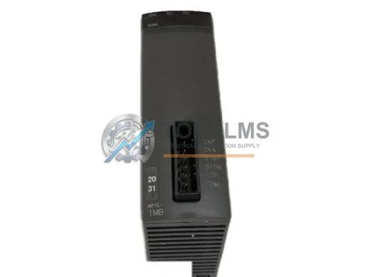
Fuji Electric NP1L-TMB ruggedized operator interface module for MICREX-NX PLC. EMI-resistant, industrial-grade. In stock, tested, 12-month warranty. Fast ship.
Molex PCU-DPI ruggedized DeviceNet-to-DPI gateway module. Reliable fieldbus communication for harsh industrial environments. 12-month warranty. In stock.
KULICKE & SOFFA 8001-4170 ruggedized serial communication interface module for wire bonder controllers. In stock, tested, 12-month warranty. Fast global shipping.
Click Quote This Model and the Part Number field will auto-fill with NP1L-RJ1.