Product Overview
Bently Nevada 190501-20-00-04 Velomitor CT: Seamless Replacement & Upgrade Solution for Legacy Vibration Monitoring Systems
When your existing condition monitoring infrastructure relies on the Bently Nevada Velomitor CT seismic velocity transducer — model 190501-20-00-04 — and the original unit reaches end-of-life, faces calibration failure, or is simply discontinued from your regional distributor’s stock, the migration path must be precise. This listing provides a direct, specification-matched replacement for the 190501-20-00-04, engineered to integrate into Bently Nevada 3500 Series machinery protection systems without requiring rewiring, reconfiguration of the monitoring rack, or changes to your existing alarm and trip setpoints.
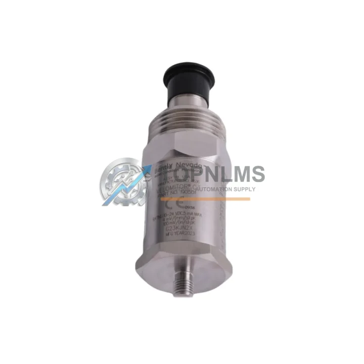
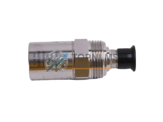
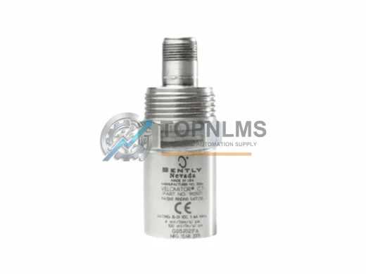
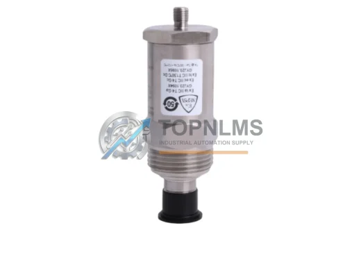
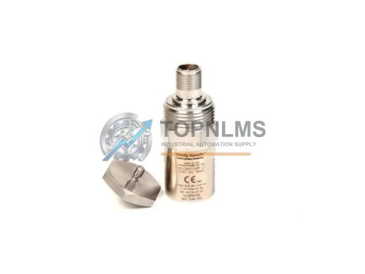
The Velomitor CT is a piezoelectric velocity transducer designed for absolute vibration measurement on large rotating machinery — turbines, compressors, pumps, fans, and gearboxes — where casing or bearing housing vibration must be continuously monitored. Its 4-pin MIL-C-5015 connector, integral cable, and 100 mV/in/s sensitivity make it a plug-compatible replacement for earlier Velomitor models used across decades of industrial installations.
Compatibility Comparison Table
| Parameter |
Legacy / Replaced Model |
190501-20-00-04 (This Unit) |
| Brand |
Bently Nevada |
Bently Nevada |
| Series |
Velomitor / Velomitor CT |
Velomitor CT |
| SKU / Part Number |
190501-xx-xx-xx variants |
190501-20-00-04 |
| Measurement Type |
Absolute Seismic Velocity |
Absolute Seismic Velocity |
| Sensitivity |
100 mV/in/s (nominal) |
100 mV/in/s (nominal) |
| Frequency Range |
2–1000 Hz |
2–1000 Hz |
| Connector Type |
MIL-C-5015 4-pin |
MIL-C-5015 4-pin |
| Cable Length |
Varies by suffix |
20 ft (suffix -20) |
| Mounting |
Stud mount, ¼-28 UNF |
Stud mount, ¼-28 UNF |
| Compatible Monitor |
3500/42M, 3500/45, 3300 Series |
3500/42M, 3500/45, 3300 Series |
| Communication Protocol |
Analog 4–20 mA / voltage output |
Analog 4–20 mA / voltage output |
| Installation Space |
Standard bearing housing footprint |
Identical footprint — no modification |
| Replacement Recommendation |
Direct drop-in replacement |
✔ Confirmed compatible |
| Warranty |
N/A (legacy/EOL) |
12-Month Warranty |
Seamless Upgrade Solutions: Migration-Ready Components for Your 3500 Series System
A successful migration from a failed or discontinued Velomitor unit rarely involves a single component. In most field scenarios, the 190501-20-00-04 transducer is one element within a broader Bently Nevada 3500 Series rack-based protection system. During the replacement process, engineers frequently audit adjacent components to ensure the entire monitoring chain remains reliable.
The 3500/42M Proximitor/Seismic Monitor is the most common companion module — it receives the velocity signal from the Velomitor CT and processes it against configured alarm and trip thresholds. If your 3500/42M has accumulated years of service alongside the failed transducer, this is an ideal time to verify its calibration or source a tested spare. Similarly, the 3500/20 Rack Interface Module (RIM) governs communication between the 3500 rack and your plant DCS or SCADA system; confirming its firmware version and Modbus or Ethernet/IP configuration ensures uninterrupted data flow after the transducer swap.
For installations where the transducer cable routing passes through conduit or junction boxes, the 3500 Series I/O Module terminal blocks and field wiring termination assemblies should be inspected. Corroded terminals or damaged cable shields are a frequent secondary cause of signal noise after a transducer replacement. If the existing cable run exceeds the standard 20-foot length of the 190501-20-00-04, a Bently Nevada extension cable assembly with matched impedance characteristics is required to preserve signal integrity to the monitor input.
In turbine and compressor applications, the Velomitor CT often operates alongside 3300 XL 8mm proximity probes and 3300 XL extension cables monitoring shaft radial and axial position. These proximity systems share the same 3500 rack infrastructure and are subject to the same environmental stresses. Sourcing tested spares for the proximity probe driver electronics — the 3300 XL proximitor — during a planned Velomitor replacement outage is a common best practice that reduces future unplanned downtime.
Where the 3500 rack communicates with a GE Mark VI or Emerson DeltaV DCS via hardwired I/O or serial Modbus, verifying the 3500/92 Communication Gateway Module configuration after any rack disturbance is essential. The gateway maps transducer channel data to process variables in the DCS historian, and a channel reassignment during replacement can silently corrupt trend data if not validated. For older installations still using a 3500/05 Power Supply Module with aging capacitors, a concurrent power supply replacement eliminates a common failure mode that can mimic transducer faults.
Finally, if your site is transitioning from the legacy 3300 Series monitoring platform to the current 3500 architecture, the 190501-20-00-04 Velomitor CT is fully compatible with both generations, making it an ideal bridge component during a phased rack modernization program.
Retrofit Guidance FAQ
Q: Can I replace the 190501-20-00-04 without reconfiguring the 3500/42M monitor?
A: Yes. The Velomitor CT 190501-20-00-04 is a direct sensitivity-matched replacement. Provided your existing 3500/42M channel is configured for a 100 mV/in/s velocity transducer, no software or hardware reconfiguration is required. Alarm and trip setpoints remain valid.
Q: Is the wiring connector compatible with my existing field cable?
A: The 190501-20-00-04 uses a standard MIL-C-5015 4-pin connector. If your installation uses the Bently Nevada mating connector on the field cable side, the connection is plug-compatible. Inspect the cable shield termination at the junction box for continuity before reconnecting.
Q: What communication protocol does this transducer use?
A: The Velomitor CT is a passive analog sensor. It outputs a voltage signal proportional to casing velocity, which is conditioned by the 3500/42M monitor. The monitor then communicates digitally to your DCS or SCADA via the 3500/92 gateway using Modbus RTU, Modbus TCP, or Ethernet/IP depending on your rack configuration. No changes to the communication protocol are required when replacing the transducer.
Q: Does the physical mounting footprint match the original unit?
A: Yes. The 190501-20-00-04 uses a ¼-28 UNF stud mount, identical to all Velomitor CT variants. No machining or adapter plates are required. Torque the mounting stud to the manufacturer’s specification (typically 10–15 in-lb) to ensure proper mechanical coupling and accurate vibration measurement.
Q: How do I validate the replacement during commissioning?
A: After installation, apply a known vibration reference (calibration shaker or portable vibration calibrator) to the bearing housing and verify the 3500/42M channel reading matches the expected value within ±5%. Compare the live trend in your DCS historian against pre-replacement baseline data to confirm signal quality. Clear any latched alarms in the 3500 rack before returning the machine to service.
Q: Can this unit replace transducers in a 3300 Series rack?
A: Yes. The Velomitor CT is backward-compatible with 3300 Series monitor inputs configured for velocity transducer input. Verify the channel input impedance setting in the 3300 monitor matches the transducer output impedance specification.
Warranty Assurance
Every Bently Nevada 190501-20-00-04 unit shipped from TOPNLMS is covered by a 12-month warranty from the date of delivery. Prior to shipment, each unit undergoes functional verification including sensitivity check, connector integrity inspection, and cable continuity test. Units are packaged in anti-static, shock-resistant packaging with individual serial number documentation.
In the event of a warranty claim, TOPNLMS provides a replacement unit or full refund within the warranty period. Our technical team is available to support installation verification, signal validation, and compatibility confirmation before and after purchase. Typical order processing is 1–3 business days, with express shipping options available for urgent plant maintenance requirements.
For volume procurement, spare parts programs, or site-wide condition monitoring audits, contact our industrial automation team directly to discuss pricing, lead times, and consignment stock arrangements.