Product Overview
Bently Nevada 190501-19-00-04 Velomitor CT Replacement: Seamless Transition from Legacy Vibration Monitoring Systems
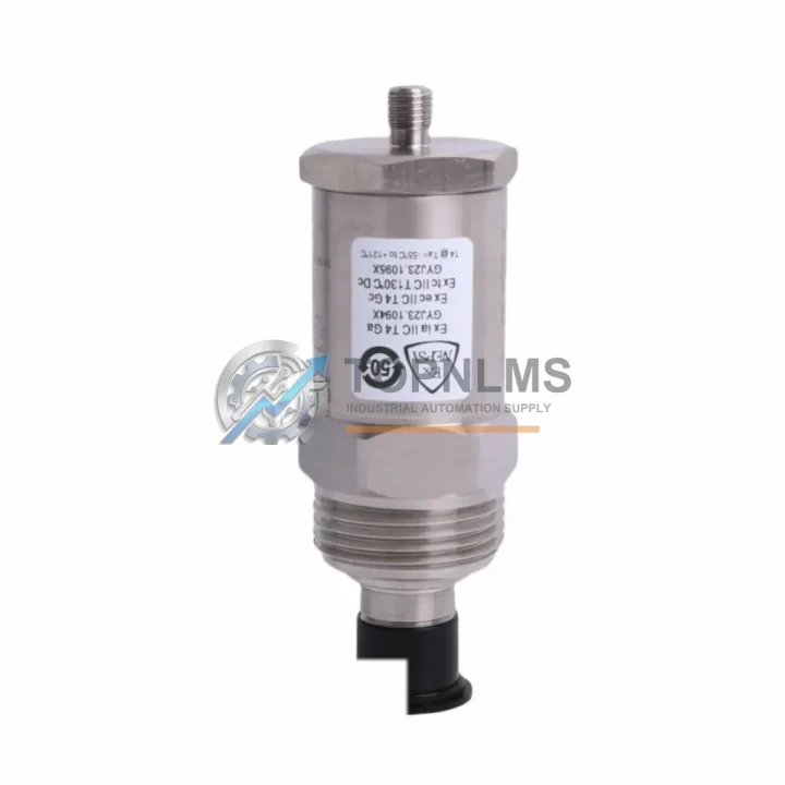
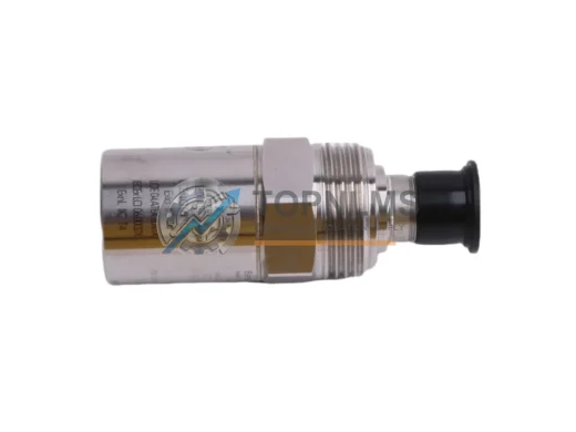
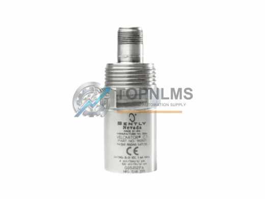
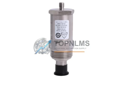
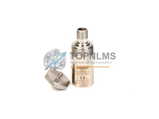
The Bently Nevada 190501-19-00-04 Velomitor CT Velocity Transducer is a precision piezoelectric velocity sensor engineered for continuous machinery protection in rotating equipment applications. As legacy vibration monitoring systems age and original Bently Nevada 190501 series units reach end-of-service life, plant engineers and reliability teams face increasing pressure to source verified replacement units that maintain full compatibility with existing wiring, signal conditioning, and data acquisition infrastructure — without triggering costly system-wide overhauls or extended production shutdowns.
TOPNLMS stocks the 190501-19-00-04 as a direct replacement and upgrade solution for facilities operating Bently Nevada 3300 Series machinery protection systems, Proximitor/Seismoprobe monitoring racks, and integrated plant asset management platforms. Whether you are replacing a failed unit on a critical compressor train, upgrading a turbine monitoring loop, or building a spare parts inventory for a refinery turnaround, this Velomitor CT variant delivers the measurement accuracy and environmental ruggedness your application demands.
Compatibility Comparison Table
| Parameter |
Legacy / Outgoing Model |
190501-19-00-04 (This Unit) |
| Part Number |
190501-xx-xx-xx (earlier configs) |
190501-19-00-04 |
| Sensor Type |
Piezoelectric Velocity |
Piezoelectric Velocity (Velomitor CT) |
| Output Signal |
4–20 mA / voltage (config-dependent) |
4–20 mA compatible, low-impedance voltage output |
| Frequency Range |
Varies by legacy suffix |
2–1000 Hz (standard Velomitor CT range) |
| Connector / Interface |
2-pin MIL-spec or bare cable |
2-pin MIL-spec connector (direct swap) |
| Mounting |
1/4-28 UNF stud or adhesive pad |
1/4-28 UNF stud mount (standard) |
| Operating Temperature |
–40 °C to +121 °C |
–40 °C to +121 °C |
| System Compatibility |
3300 Series, legacy Proximitor racks |
3300 Series, 3500 Series (with adapter), ADRE systems |
| Communication Protocol |
Analog 4–20 mA / hardwired |
Analog 4–20 mA / hardwired (no protocol change required) |
| Replacement Recommendation |
Direct drop-in for same-suffix units |
Verified compatible; wiring and calibration preserved |
| Warranty |
OEM warranty expired (legacy units) |
12-Month Warranty from TOPNLMS |
Seamless Upgrade Solutions
A successful migration from a failed or end-of-life vibration monitoring loop rarely involves a single component. When replacing the 190501-19-00-04 Velomitor CT in a Bently Nevada 3300 Series rack, field engineers typically review the entire signal chain to ensure measurement integrity is preserved from sensor to control room.
The Velomitor CT connects directly to a Bently Nevada 3300/16 Velocity Monitor or a 3300/55 Dual Velocity Monitor module seated in the 3300 Series rack. If the monitor card itself shows drift or calibration failure, it is common practice to replace both the transducer and the monitor card simultaneously to eliminate compounding error sources. The rack backplane and power supply — typically a Bently Nevada 3300/05 Power Supply — should be inspected for output voltage stability before commissioning the new transducer, as an under-voltage condition can cause the Velomitor CT to output erroneous readings that mimic mechanical faults.
For facilities migrating from older Seismoprobe or Velomitor XA installations to the Velomitor CT platform, the primary wiring change involves the cable assembly. The Bently Nevada 330130 series interconnect cable is the standard field-wiring solution for Velomitor CT installations, providing the correct impedance matching and shielding required for low-noise signal transmission in electrically noisy plant environments such as motor control centers and variable frequency drive (VFD) enclosures.
In applications where the 190501-19-00-04 is installed on equipment monitored by a Bently Nevada 3500/42M Velocity/Acceleration Monitor within a 3500 Series rack, a signal conditioning adapter may be required to bridge the analog output format. The 3500 platform supports both the Velomitor CT and the Velomitor XA, and the migration path is well-documented in Bently Nevada’s installation manuals. No PLC program changes are required when the replacement transducer maintains the same 4–20 mA output scaling.
For plants running a System 1 Evolution asset management platform or integrating vibration data into a DeltaV SIS or Honeywell Safety Manager safety instrumented system, the analog signal from the 190501-19-00-04 feeds through standard I/O modules without modification. The transducer’s output is hardware-level and protocol-agnostic, meaning no changes to OPC-UA tags, Modbus register maps, or HART device descriptors are needed during the swap.
Where physical installation space is constrained — such as in compact turbine skids or retrofit control cabinets — the Velomitor CT’s compact body profile and flexible cable exit orientation simplify reinstallation without requiring bracket modifications. If the mounting surface requires a new stud insert, a Bently Nevada 02-262610-01 mounting stud kit provides the correct thread specification for most steel and cast-iron housings.
Finally, for commissioning and loop verification after installation, a Bently Nevada portable calibrator or a compatible handheld vibration calibrator can be used to inject a known velocity signal and confirm the full signal chain — from transducer output through the monitor card to the DCS historian — is reading correctly before returning the machine to service.
Retrofit Guidance FAQ
Q: Can I replace my existing Velomitor XA with the 190501-19-00-04 without rewiring?
A: In most cases, yes. The Velomitor CT uses the same 2-pin MIL-spec connector and the same cable color convention as the Velomitor XA. Verify the cable assembly part number and confirm the monitor card input impedance specification before finalizing the swap. No rewiring is typically required for standard 3300 Series installations.
Q: Do I need to modify my PLC or DCS program after replacing the transducer?
A: No. The 190501-19-00-04 outputs a standard analog signal. As long as the replacement unit’s sensitivity (mV/mm/s or mV/in/s) matches the original, your existing scaling, alarm setpoints, and trip thresholds in the DCS or safety system remain valid. Confirm the sensitivity specification on the unit label before installation.
Q: Is the 190501-19-00-04 compatible with the Bently Nevada 3500 Series rack?
A: The Velomitor CT is natively supported by the 3300 Series. For 3500 Series installations, compatibility depends on the specific monitor module. The 3500/42M Velocity/Acceleration Monitor supports Velomitor CT inputs; consult the module’s installation manual for input configuration details.
Q: What communication protocol does this transducer use?
A: The 190501-19-00-04 is a passive analog sensor. It does not use a digital communication protocol (no HART, Modbus, or Profibus). The signal is a low-impedance voltage output that connects directly to the monitor card’s input terminals. No protocol configuration is required.
Q: How do I verify the transducer is functioning correctly after installation?
A: After installation, perform a static check by gently tapping the sensor body and observing the monitor card’s output. For a calibrated verification, use a portable vibration calibrator to inject a known velocity signal at the transducer mounting point and confirm the monitor card reading matches the expected value within the specified tolerance (typically ±5%).
Q: What is the lead time and shipping arrangement?
A: Units are in stock at our Xiamen warehouse. Standard orders ship within 1–3 business days via DHL Express, FedEx International Priority, or UPS Worldwide Expedited. Expedited same-day dispatch is available for orders confirmed before 14:00 CST. Export documentation (commercial invoice, packing list, COO) is provided with every shipment.
Warranty Assurance
Every Bently Nevada 190501-19-00-04 Velomitor CT Velocity Transducer supplied by TOPNLMS is covered by a 12-Month Warranty from the date of shipment. Our warranty program is designed to meet the procurement and quality assurance requirements of industrial plant operators, EPC contractors, and MRO purchasing teams.
Pre-shipment Testing: Each unit undergoes functional verification prior to dispatch, including output signal continuity check, connector integrity inspection, and visual examination for physical damage. Units that do not pass inspection are quarantined and not shipped.
Warranty Coverage: The 12-month warranty covers manufacturing defects, premature component failure under normal operating conditions, and connector or cable assembly faults present at the time of delivery. Damage resulting from incorrect installation, overvoltage, mechanical impact, or operation outside the specified environmental range is excluded.
Replacement Support: In the event of a warranty claim, TOPNLMS will arrange advance replacement shipment upon receipt of the failed unit and confirmation of the defect. Our target response time for warranty claims is 24–48 hours from initial notification.
After-Sales Response: Our technical support team is available via email and phone to assist with installation questions, compatibility verification, and commissioning guidance throughout the warranty period and beyond.
Procurement Assurance: TOPNLMS issues a formal warranty certificate with each order. Purchase orders, proforma invoices, and quality certificates are available upon request to support your internal procurement and quality management system (QMS) documentation requirements.