Product Overview
Bently Nevada 190501-14-00-04 Velomitor CT Upgrade Solution: Seamless Transition from Legacy Vibration Monitoring Systems
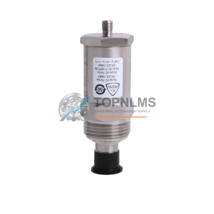
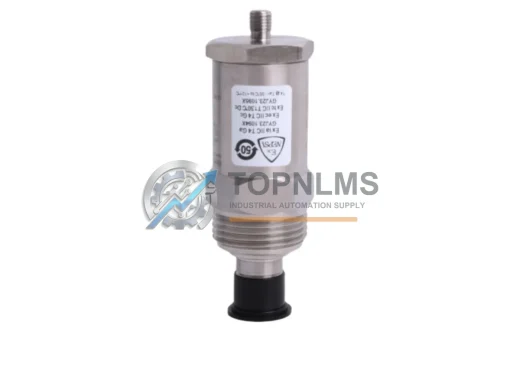
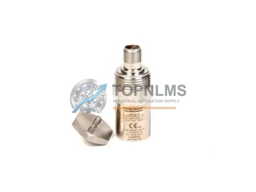
The Bently Nevada 190501-14-00-04 Velomitor CT Velocity Transducer is a precision-engineered, industry-proven sensor designed for continuous vibration monitoring of rotating machinery in critical industrial environments. As legacy condition monitoring systems reach end-of-life or become increasingly difficult to maintain, facilities operating older Bently Nevada platforms — including early-generation 3300 series monitors and discontinued 7200 series proximity systems — face mounting pressure to modernize without disrupting production. The 190501-14-00-04 provides a technically validated, drop-in-compatible upgrade path that preserves existing wiring infrastructure, rack architecture, and monitoring logic while delivering the measurement accuracy and signal integrity demanded by modern machinery protection standards.
Engineered to integrate directly with Bently Nevada’s 3500 Series Machinery Protection System, this Velomitor CT transducer outputs a velocity signal fully compatible with the 3500/42M Velocity/Acceleration Monitor and the 3500/40M Proximitor/Seismic Monitor. Facilities currently running 3500/42 or 3500/40 I/O modules can replace aging seismic sensors or discontinued velocity transducers without reprogramming monitor setpoints, reconfiguring rack backplane connections, or modifying existing Keyphasor reference signal routing. The transducer’s integral cable and connector format matches the standard field wiring used across Bently Nevada’s modular rack systems, eliminating the need for custom junction boxes or signal conditioning adapters during retrofit.
For plants migrating from older 7200 Series proximity transducer installations or decommissioning standalone vibration transmitters, the 190501-14-00-04 offers a straightforward mechanical and electrical substitution. Its compact cylindrical housing fits standard transducer mounting brackets used on turbine bearing housings, compressor casings, pump pedestals, and motor end-bells. The transducer’s sensitivity specification and frequency response range align with the input requirements of the 3500 Series velocity input cards, ensuring that existing alarm and danger setpoints remain valid after replacement without requiring a full system recalibration cycle.
Compatibility Comparison Table
| Parameter |
Legacy / Replaced Model |
190501-14-00-04 (This Unit) |
| Sensor Type |
Velocity Transducer / Seismic Sensor |
Velomitor CT Velocity Transducer |
| Compatible Monitor |
3500/42, 3500/40, 7200 Series |
3500/42M, 3500/40M, 3500 Rack |
| Output Signal |
Velocity (mV/mm/s or mV/in/s) |
Velocity (standard Bently Nevada output) |
| Connector / Cable |
Legacy field wiring (varies) |
Integral cable, standard BN connector |
| Mounting |
Standard transducer bracket |
Direct-fit, same bracket footprint |
| Communication Protocol |
Analog (4–20 mA / voltage) |
Analog, fully compatible with 3500 I/O |
| Rack Backplane |
3500 Series standard backplane |
No backplane modification required |
| Setpoint Recalibration |
Required for non-compatible replacements |
Not required — direct specification match |
| Installation Space |
Standard bearing housing / casing mount |
Same form factor, no housing modification |
| Warranty |
N/A (legacy / EOL) |
12-Month Warranty included |
Seamless Upgrade Solutions
A successful migration from a legacy vibration monitoring installation to a modernized Bently Nevada 3500 Series platform typically involves more than a single transducer swap. When replacing the 190501-14-00-04 or upgrading surrounding system components, engineers commonly address the following associated hardware in the same maintenance window to minimize future downtime risk.
The 3500/42M Velocity/Acceleration Monitor is the primary rack-mounted monitor that processes the velocity signal from the 190501-14-00-04. If the existing 3500/42 card is approaching end-of-life or showing intermittent faults, replacing it alongside the transducer ensures the entire measurement chain is renewed simultaneously. Similarly, the 3500/20 Rack Interface Module (RIM) governs communication between the 3500 rack and the plant DCS or SCADA system via Modbus RTU or Ethernet/IP; verifying RIM firmware compatibility before commissioning the new transducer prevents protocol handshake failures during system restart.
Plants running Bently Nevada’s System 1 Evolution condition monitoring software should confirm that the transducer’s channel configuration in the software database is updated to reflect the 190501-14-00-04’s sensitivity and measurement range. The 3500/22M Transient Data Interface (TDI) module, where installed, captures startup and shutdown transient data and must be verified for correct channel mapping after any transducer replacement on the same rack slot.
For facilities also upgrading proximity measurement channels, the 3300 XL 8mm Proximity Transducer System (including driver, extension cable, and probe) is a common companion replacement when decommissioning older 7200 Series proximity installations on the same machine train. The 3500/40M Proximitor/Seismic Monitor handles both proximity and seismic inputs and may be present in the same rack as the velocity monitor, making it a logical concurrent upgrade candidate.
Field wiring integrity is critical during any transducer retrofit. Technicians should inspect and, where necessary, replace Bently Nevada armored extension cables and terminal junction boxes between the transducer and the rack I/O card. Corroded or mechanically damaged cable assemblies are a leading cause of post-installation signal noise and false alarms. Where signal isolation is required between the transducer output and a third-party DCS analog input card, a galvanic signal isolator (DIN-rail mounted, 4–20 mA loop-powered) can be inserted in the field wiring loop without affecting the 3500 monitor’s measurement accuracy.
Finally, for sites integrating the upgraded monitoring system with a Honeywell Experion PKS, ABB System 800xA, or Emerson DeltaV DCS platform, confirming the 3500 rack’s communication module configuration — whether Modbus TCP, OPC DA, or hardwired 4–20 mA — ensures that the new transducer’s data is correctly reflected in the plant historian and alarm management system from the first moment of commissioning.
Retrofit Guidance FAQ
Q: Will the 190501-14-00-04 work with my existing 3500 rack wiring without modification?
A: Yes. The Velomitor CT uses the standard Bently Nevada field wiring connector and cable format. In most installations, the transducer can be connected directly to the existing field wiring without splicing, re-terminating, or adding signal conditioning hardware. Verify cable continuity and insulation resistance before reconnecting.
Q: Do I need to reprogram the 3500/42M monitor after replacing the transducer?
A: No reprogramming is required if the replacement transducer matches the original sensitivity specification. Alarm and danger setpoints, full-scale range, and OK relay logic configured in the 3500 rack remain valid. A functional verification test (bump test or signal injection) is recommended after installation to confirm correct operation before returning the machine to service.
Q: Is the 190501-14-00-04 compatible with Modbus RTU communication from the 3500 rack to the DCS?
A: The transducer itself is an analog sensor; communication protocol compatibility is governed by the 3500/20 Rack Interface Module. The 190501-14-00-04 is fully compatible with all 3500 rack communication configurations, including Modbus RTU, Modbus TCP, and hardwired 4–20 mA retransmission outputs.
Q: What if the physical mounting location has limited space?
A: The 190501-14-00-04 shares the same cylindrical housing dimensions as the transducers it replaces in standard Bently Nevada installations. No modification to the bearing housing boss, mounting bracket, or cable conduit entry is required. For installations with non-standard mounting configurations, contact our technical team before ordering.
Q: Can this transducer replace a unit from a 7200 Series installation?
A: The 190501-14-00-04 is designed for the 3500 Series platform. Migration from a 7200 Series installation requires verifying that the associated monitor card (3500/40M or 3500/42M) is present in the rack and correctly configured for velocity input. In most cases, the 7200 Series monitor card must be replaced with the appropriate 3500 Series card as part of the migration.
Q: How should I handle commissioning and system testing after installation?
A: After mechanical installation and wiring connection, perform a channel OK verification using the 3500 rack’s front-panel display or System 1 software. Conduct a signal path check by applying a known vibration source or signal injector to confirm that the measured value, alarm response, and relay output all function correctly before releasing the machine for normal operation.
Warranty Assurance
Every Bently Nevada 190501-14-00-04 Velomitor CT Velocity Transducer supplied by TOPNLMS is backed by a 12-month warranty covering manufacturing defects, component failure, and performance deviations from published specifications. Prior to shipment, each unit undergoes a multi-point outgoing inspection that includes visual examination, connector integrity verification, and electrical performance testing to confirm that the transducer meets Bently Nevada’s original factory specifications.
In the event of a warranty claim, TOPNLMS provides a direct replacement or full refund within the warranty period. Our after-sales response team is available to assist with technical troubleshooting, installation guidance, and documentation support. Replacement units are dispatched with priority handling to minimize the impact on your maintenance schedule and machine availability.
For procurement teams requiring documentation, we can provide inspection reports, test certificates, and shipping records upon request. All units are shipped with appropriate protective packaging to prevent transit damage, and tracking information is provided at the time of dispatch. We support urgent orders with expedited shipping options to destinations worldwide, with typical lead times from our Xiamen warehouse communicated at the time of order confirmation.
TOPNLMS is committed to supporting industrial facilities through every stage of the upgrade and replacement process — from pre-order technical consultation through post-installation commissioning support — ensuring that your investment in modernized condition monitoring delivers reliable, long-term performance.
© 2026 TOPNLMS. All rights reserved.
Original Source: https://topnlms.com
Contact: [email protected] | +86 18359293191