Product Overview
Bently Nevada 190501-11-99-01 Upgrade for Velomitor CT: Seamless Transition from Legacy Vibration Monitoring Systems
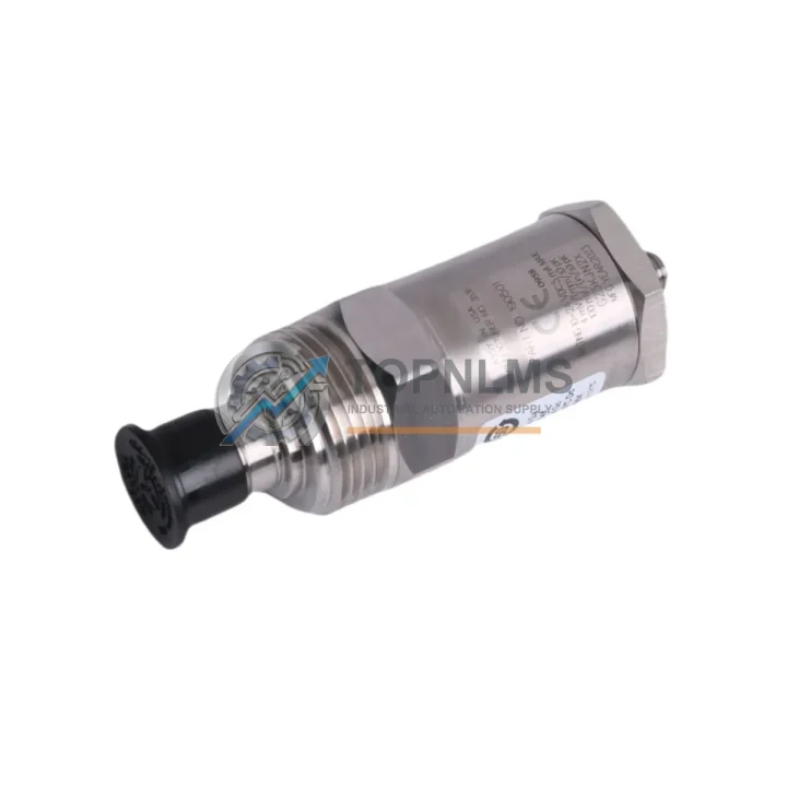
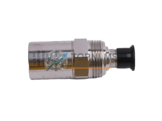
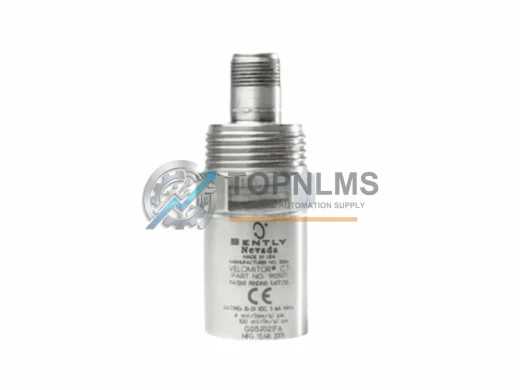
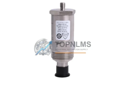
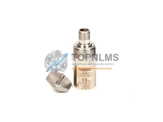
The Bently Nevada 190501-11-99-01 Velomitor CT Velocity Transducer is a precision seismic velocity sensor engineered for continuous machinery health monitoring in rotating equipment applications. As legacy vibration monitoring installations age and original Velomitor CT units reach end-of-service life, facilities engineers and reliability teams face the challenge of maintaining measurement continuity without disrupting existing wiring infrastructure, rack architecture, or data acquisition configurations. This replacement and upgrade solution is designed to eliminate that friction — delivering a drop-in compatible unit that preserves your existing signal chain while meeting current performance specifications.
Whether your plant is running a Bently Nevada 3500 Series rack-based monitoring system, a legacy 7200 Series proximitor loop, or a standalone data collector integration, the 190501-11-99-01 is engineered to restore full measurement capability with minimal intervention. The Velomitor CT outputs a velocity signal in mV/mm/s, compatible with standard Bently Nevada 3500/42M velocity and acceleration monitor cards, allowing direct substitution without reconfiguring monitor setpoints or alarm thresholds in your System 1 or System 1 Evolution software environment.
Compatibility Comparison Table
| Parameter |
Legacy / Outgoing Unit |
190501-11-99-01 (This Unit) |
| Model / SKU |
Velomitor CT (earlier revision) |
190501-11-99-01 |
| Sensor Type |
Seismic Velocity (Electrodynamic) |
Seismic Velocity (Piezoelectric / CT) |
| Output Signal |
mV/mm/s velocity |
mV/mm/s velocity (compatible) |
| Connector Interface |
2-pin MIL-C-5015 style |
2-pin MIL-C-5015 style (direct fit) |
| Mounting Thread |
1/4-28 UNF or M8 (application-dependent) |
1/4-28 UNF (confirm per installation) |
| Compatible Monitor Cards |
3500/42M, 3500/40M |
3500/42M, 3500/40M (verified) |
| Operating Temperature |
-40°C to +121°C |
-40°C to +121°C |
| Installation Space |
Standard bearing housing pad |
Identical footprint — no machining required |
| Communication / Protocol |
Analog 4–20 mA / mV output |
Analog 4–20 mA / mV output (compatible) |
| Replacement Recommendation |
Direct substitution |
✓ Confirmed drop-in replacement |
| Warranty |
— |
12-Month Warranty (from ship date) |
Seamless Upgrade Solutions
A successful Velomitor CT replacement rarely involves a single component in isolation. In most 3500 Series installations, the 190501-11-99-01 operates as part of a broader vibration monitoring loop that includes the Bently Nevada 3500/42M Velocity and Acceleration Monitor card seated in the 3500 rack, which processes the transducer’s analog output and compares it against configured alert and danger setpoints. If the monitor card itself is approaching end-of-life or showing calibration drift, replacing it alongside the transducer ensures the entire measurement chain is restored to factory specification.
The transducer connects to the monitor card via a dedicated field wiring termination. In installations using the Bently Nevada 3500/20 Rack Interface Module, the system’s communication with the host DCS or SCADA platform — typically over Modbus RTU or the proprietary Bently Nevada communication protocol — remains unaffected by a transducer swap, provided the monitor card configuration is preserved. Engineers performing the swap should export the rack configuration from System 1 prior to any hardware removal to protect setpoint data.
For facilities where the existing cable run between the transducer and the rack junction box is also being replaced, the Bently Nevada 330130 Extension Cable series provides the correct impedance-matched, shielded interconnect to maintain signal integrity over long cable runs in electrically noisy plant environments. Pairing the new transducer with a fresh cable assembly eliminates a common source of intermittent faults that can be misdiagnosed as transducer failure.
In applications where the 190501-11-99-01 is being installed as part of a broader machinery protection upgrade — for example, migrating from a legacy 7200 Series monitoring system to the current 3500 platform — the Bently Nevada 3500/15 Power Supply Module and 3500/05 System Rack form the backbone of the new installation. The power supply module provides the regulated DC supply required by the velocity monitor cards, while the system rack accommodates up to 14 I/O and monitor modules in a standard 19-inch panel cutout, making it compatible with most existing control cabinet layouts without structural modification.
Where the upgrade scope extends to proximity probe measurements on the same machine train — for example, adding shaft relative displacement monitoring alongside the seismic velocity channel — the Bently Nevada 3300 XL 8mm Proximity Transducer System integrates directly into the same 3500 rack architecture, sharing the common power bus and communication backplane. This allows a single rack to consolidate velocity, acceleration, and proximity measurements, reducing panel space requirements and simplifying the overall wiring layout in the control cabinet.
For sites requiring portable verification of the replacement transducer’s output prior to returning the machine to service, a Bently Nevada ADRE 408 DSPi Data Acquisition System or equivalent portable data collector can be used to capture a baseline vibration spectrum immediately after installation. This baseline record supports future trending analysis and provides documented evidence of acceptable vibration levels at commissioning — a requirement under many plant reliability and insurance audit frameworks.
Retrofit Guidance FAQ
Q: Will the 190501-11-99-01 work with my existing field wiring without modification?
In the majority of installations, yes. The Velomitor CT uses a standard 2-conductor shielded cable terminated at a MIL-C-5015 style connector. Provided the existing cable is undamaged and the connector is in good condition, the replacement unit can be connected directly. Inspect the cable insulation and shield continuity before reinstalling — degraded shielding is a common source of noise on velocity channels in high-vibration environments.
Q: Do I need to reconfigure the 3500/42M monitor card after replacing the transducer?
Not if the replacement unit is the same model revision and the monitor card configuration has not been altered. The 3500/42M stores its configuration in non-volatile memory. However, it is best practice to verify the full-scale range, alert, and danger setpoints in System 1 after any hardware change and to perform a functional test by observing the channel output with the machine at known operating speed before returning to automatic protection mode.
Q: Is the physical mounting footprint identical to the unit being replaced?
The 190501-11-99-01 uses the same 1/4-28 UNF mounting thread as the standard Velomitor CT. No machining or adapter is required for installations on standard bearing housing mounting pads. Confirm the thread specification against your installation drawing before ordering if your application uses the metric M8 mounting variant.
Q: What communication protocols are supported?
The transducer itself is an analog device — it outputs a velocity-proportional voltage signal. Protocol-level communication (Modbus, OPC-UA, Ethernet/IP) is handled by the 3500 rack’s interface modules, not the transducer. Replacing the 190501-11-99-01 has no impact on the rack’s communication configuration or the data path to your DCS or historian.
Q: Can this unit be used as a spare for multiple machines on the same site?
Yes. The 190501-11-99-01 is a universal spare for any installation using the Velomitor CT in the same configuration. Maintaining one or two units in site inventory is standard practice for critical rotating equipment where unplanned downtime carries significant production cost. Units should be stored in the original packaging in a dry, temperature-controlled environment and inspected prior to installation if stored for more than 24 months.
Q: What is the lead time and how is the unit shipped?
Units in stock at our Xiamen warehouse are typically dispatched within 1–2 business days of order confirmation. International shipments are sent via DHL Express or FedEx International Priority with full tracking. Export documentation including commercial invoice, packing list, and certificate of conformance is provided with every shipment.
Warranty Assurance
Every 190501-11-99-01 Velomitor CT Velocity Transducer supplied by TOPNLMS is covered by a 12-month warranty from the date of shipment. Prior to dispatch, each unit undergoes functional verification including output signal check, connector integrity inspection, and physical condition assessment. Units that do not meet our outgoing quality standard are quarantined and not shipped.
In the event of a warranty claim, our after-sales team responds within one business day. Confirmed defective units are replaced at no charge, with return shipping costs covered for orders where the defect is confirmed as a manufacturing or handling issue on our side. We do not charge restocking fees on warranty returns.
For procurement teams requiring documentation, we can provide a test report, certificate of conformance, or country-of-origin declaration upon request at the time of order. These documents support incoming inspection processes and are accepted by most plant quality management systems.
TOPNLMS maintains stock of high-demand Bently Nevada components specifically to support emergency replacement scenarios. If you are managing a critical machine outage, contact us directly by phone or email for priority processing.