Product Overview
AMCI SD17060B-25 Replacement & Upgrade Solution for SD Series: Smooth Transition from Legacy Stepper Drive Systems
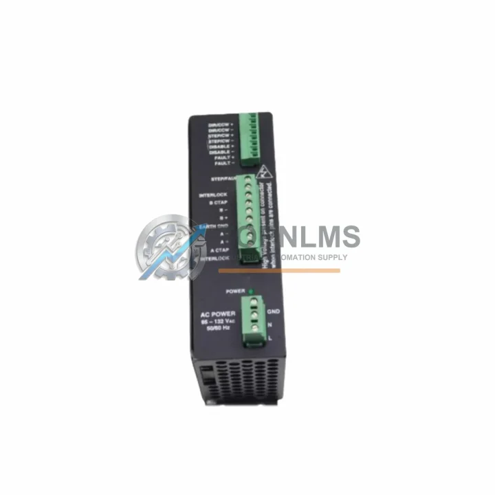
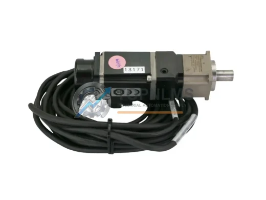
The AMCI SD17060B-25 is a high-performance stepper motor driver from AMCI’s SD Series, designed for precise motion control in industrial automation environments. For facilities running aging or discontinued stepper drive platforms — including earlier AMCI SD-series variants, third-party step/direction drives, or legacy pulse-train motion controllers — the SD17060B-25 offers a validated, drop-in upgrade path that minimizes engineering rework, reduces downtime, and preserves existing wiring infrastructure wherever possible.
Whether your current system relies on an older AMCI SD7540 or SD17060 without the -25 suffix, or you are migrating from a competing stepper drive platform integrated into a Rockwell Automation, Siemens, or Mitsubishi PLC architecture, the SD17060B-25 is engineered to accept standard step/direction pulse signals, making it broadly compatible with most motion-capable PLCs and motion controllers already deployed in your control cabinet.
Compatibility Comparison Table
| Parameter |
Legacy / Replaced Model |
AMCI SD17060B-25 |
| Typical Replaced Models |
AMCI SD17060, SD7540, SD7540E; 3rd-party step/dir drives |
SD17060B-25 (current production) |
| Input Voltage Range |
Varies (typically 24–48 VDC) |
12–70 VDC |
| Output Current (Peak) |
Varies by model |
6.0 A peak per phase |
| Step Resolution |
Fixed or limited microstepping |
Up to 25,000 steps/rev (software selectable) |
| Control Interface |
Step/Direction pulse train |
Step/Direction pulse train (compatible) |
| Communication Protocol |
Typically none or RS-232 |
RS-232 configuration port |
| Mounting / Form Factor |
DIN rail or panel mount |
DIN rail mount, compact footprint |
| Motor Phase Wiring |
4-wire or 8-wire stepper motor |
4-wire or 8-wire stepper motor (compatible) |
| Fault Output |
Limited or absent |
Dedicated fault output signal |
| Replacement Recommendation |
End-of-life / discontinued |
Direct replacement — minimal rewiring required |
| Warranty |
Expired / unavailable |
12-Month Warranty from TOPNLMS |
Seamless Upgrade Solutions
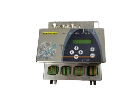
A successful migration to the AMCI SD17060B-25 typically involves more than swapping the drive itself. In most retrofit projects, engineers also evaluate the upstream motion command source — commonly a dedicated AMCI ANF series network stepper module or an AMCI 2240 series stepper indexer card installed in a Rockwell ControlLogix or CompactLogix rack. If your existing motion controller outputs standard step and direction signals, the SD17060B-25 will accept them without firmware changes on the controller side.
On the power supply side, the SD17060B-25 accepts a wide 12–70 VDC input range, which means most existing 24 VDC or 48 VDC cabinet power supplies — including common AMCI or third-party DIN rail switching power supplies — remain fully usable. There is no need to resize or replace the power distribution block or circuit breaker in most standard control cabinet configurations.
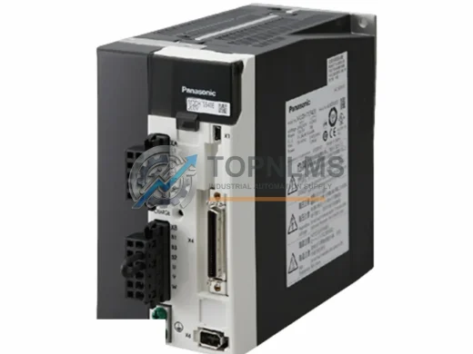
For wiring, the motor phase connections (A+, A−, B+, B−) follow the industry-standard four-wire or eight-wire stepper motor convention. If you are replacing an older AMCI SD17060 or a comparable drive from another manufacturer, your existing motor cable and terminal block wiring can typically be reused with only minor label verification. The enable, step, and direction signal lines connect via the same logic-level interface, compatible with 5 V or 24 V PLC output cards commonly found in Siemens S7-300, Mitsubishi FX, or Allen-Bradley MicroLogix control panels.
In applications where the SD17060B-25 is installed alongside other AMCI SD Series drives — for example, in a multi-axis gantry, conveyor indexing system, or rotary table — the drives share the same RS-232 configuration utility, simplifying parameter backup and restoration across axes. Engineers migrating from a mixed-brand drive environment often standardize on the SD Series platform at this stage, consolidating spare parts inventory and reducing technician training requirements.
Signal isolation is another consideration in retrofit projects. Where the existing control cabinet uses signal isolators or optocoupler barriers between the PLC output card and the drive input, these components are generally compatible with the SD17060B-25’s input specifications and do not require replacement. In noise-sensitive environments — such as those with large VFDs, servo amplifiers, or high-current motor starters in the same enclosure — maintaining proper cable shielding and grounding practices remains essential and is unchanged by the drive substitution.
For applications that previously used an AMCI SMD or NX series networked stepper module with EtherNet/IP or Modbus RTU communication, the SD17060B-25 serves as the drive stage in a split architecture, where the network module handles the PLC interface and the SD17060B-25 handles the motor current. This architecture is common in distributed I/O panels and remote control cabinets where minimizing network node count is a priority.
Retrofit Guidance FAQ
Q: Can I reuse my existing stepper motor wiring when replacing with the SD17060B-25?
A: In most cases, yes. The SD17060B-25 uses the standard A+/A−/B+/B− four-wire motor phase convention. If your existing motor is a standard bipolar or unipolar stepper wired in four-wire or eight-wire configuration, the existing cable can be reused. Verify phase resistance and current rating against the drive’s output specifications before powering up.
Q: Is the step/direction interface compatible with my existing PLC output card?
A: The SD17060B-25 accepts step and direction signals from both 5 V TTL and 24 V sourcing/sinking PLC output cards. This covers the majority of motion-capable digital output modules from Rockwell, Siemens, Mitsubishi, Omron, and Schneider Electric. Confirm your PLC output card’s signal voltage and current drive capability against the drive’s input specifications in the AMCI datasheet.
Q: Do I need to modify my PLC program when switching to the SD17060B-25?
A: No PLC program changes are required if your existing program generates standard step and direction pulse outputs. The SD17060B-25 is transparent to the motion controller — it responds to pulse trains identically to the drive it replaces. Microstepping resolution is configured via the RS-232 port using AMCI’s configuration software, not through the PLC program.
Q: Will the SD17060B-25 fit in the same DIN rail slot as my existing drive?
A: The SD17060B-25 uses a compact DIN rail mount form factor. In most standard 35 mm DIN rail control cabinets, it will fit within the same or similar footprint as previous SD Series drives. Measure the available rail space and compare with the SD17060B-25 dimensional drawing before installation if cabinet space is constrained.
Q: What communication protocol does the SD17060B-25 use for configuration?
A: Configuration is performed via RS-232 serial connection using AMCI’s PC-based configuration utility. This is used for setting microstepping resolution, current levels, and idle current reduction — not for real-time motion commands. Real-time control remains via the step/direction pulse interface from your PLC or motion controller.
Q: How do I handle the transition from a networked stepper module to the SD17060B-25?
A: If you are migrating from a fully networked AMCI module (EtherNet/IP or Modbus RTU) to a step/direction architecture using the SD17060B-25, you will need a motion-capable PLC output card or a standalone indexer to generate the pulse train. AMCI’s ANF or 2240 series indexer modules are designed for this purpose and integrate directly with the SD17060B-25 in a split-architecture configuration.
Warranty Assurance
Every AMCI SD17060B-25 unit shipped by TOPNLMS is covered by a 12-month warranty from the date of delivery. Prior to shipment, each unit undergoes functional verification including power-on testing, output current confirmation, and signal interface check. Units that do not pass inspection are not shipped.
In the event of a confirmed defect within the warranty period, TOPNLMS provides replacement support with priority processing for industrial customers to minimize production impact. Our after-sales response target is within one business day for warranty claims submitted via email or phone.
We maintain in-stock inventory of the SD17060B-25 to support same-day or next-business-day dispatch for urgent replacement orders. Shipping is available from our Xiamen warehouse to domestic and international destinations, with tracking provided for all shipments.
For procurement teams requiring documentation, we can provide product test records, packing lists, and commercial invoices upon request. Volume orders and standing purchase agreements are supported for MRO and spare parts programs.