Product Overview
Allen-Bradley 20G14NC104JA0NNNNN PowerFlex 755 Upgrade Solution: Seamless Transition from Legacy Drive Systems
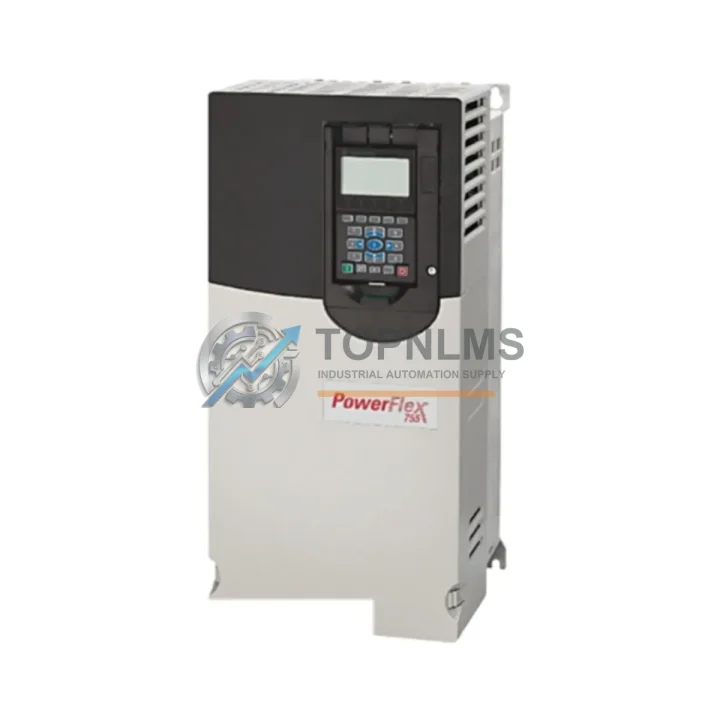
The Allen-Bradley 20G14NC104JA0NNNNN is a PowerFlex 755 AC Variable Frequency Drive rated at 104A, 480V, Frame 4, designed for demanding industrial motion control applications. As legacy drive platforms reach end-of-life or become increasingly difficult to source, facilities running older PowerFlex 700, PowerFlex 40, or PowerFlex 400 series drives face mounting pressure to modernize without disrupting production. The 20G14NC104JA0NNNNN provides a technically sound migration path — preserving existing wiring infrastructure, control logic, and communication architecture while delivering the performance and diagnostics expected of a current-generation drive platform.
For engineers managing a retrofit or emergency replacement, the PowerFlex 755 platform is engineered to minimize re-engineering effort. The drive accepts standard three-phase 480V AC input and delivers variable-frequency output across a wide load range, making it suitable for pump, fan, compressor, conveyor, and general-purpose motor control applications. Frame 4 physical dimensions align closely with prior-generation Frame 4 enclosures, reducing the need for control cabinet modifications or custom mounting brackets during a like-for-like swap.
Compatibility Comparison Table
| Parameter |
Legacy / Outgoing Model |
20G14NC104JA0NNNNN (PowerFlex 755) |
| Typical Predecessor SKUs |
20BD106A0AYNANC0 (PF700), 22C-D105A103 (PF400) |
20G14NC104JA0NNNNN |
| Voltage Rating |
480V AC (3-phase) |
480V AC (3-phase) |
| Output Current |
~100–106A (varies by predecessor) |
104A continuous |
| Frame Size |
Frame 4 (varies) |
Frame 4 |
| Communication Options |
DeviceNet, DH+, RS-232 (legacy) |
EtherNet/IP, DeviceNet, ControlNet (via option card) |
| Control Interface |
HIM module (legacy keypad) |
20-HIM-A6 / 20-HIM-C6S compatible |
| I/O Terminal Wiring |
Standard screw-terminal block |
Compatible screw-terminal layout; verify signal mapping |
| Programming Tool |
DriveExplorer / DriveExecutive |
Studio 5000 / Connected Components Workbench |
| Mounting |
Panel or cabinet mount |
Panel or cabinet mount (same footprint) |
| Warranty |
N/A (end-of-life) |
12-Month Warranty from TOPNLMS |
Seamless Upgrade Solutions
A successful migration to the 20G14NC104JA0NNNNN typically involves more than a drive swap. In most retrofit projects, the 20-750-ENETR EtherNet/IP dual-port option card is installed to replace legacy DeviceNet or DH+ communication, enabling the drive to integrate directly into a Logix-based control architecture without additional protocol converters. Where the existing system relied on a 1747-L553 SLC 5/05 or 1756-L71 ControlLogix processor for speed reference and fault monitoring, the PowerFlex 755 communicates natively over EtherNet/IP, simplifying the Add-On Instruction (AOI) integration in Studio 5000.
On the I/O side, facilities often retain existing 1756-IB16 digital input modules and 1756-OF8 analog output modules mounted in a 1756-A10 chassis, with the drive receiving 4–20 mA speed reference signals through its onboard analog input terminals. Signal isolation between the PLC analog output and the drive input is recommended when cable runs exceed 15 meters; a DIN-rail-mounted signal isolator or 1492-AIFM8-F-5 analog interface module can be inserted without rewiring the field instrumentation.
For facilities upgrading from a legacy control cabinet that housed a PowerFlex 700 alongside a 1606-XLP power supply and 1492-W4 terminal blocks, the Frame 4 footprint of the 20G14NC104JA0NNNNN allows direct panel replacement with minimal busbar or cable tray modification. The drive’s internal EMC filter and built-in brake IGBT (where applicable) reduce the need for external components that were previously mounted separately.
Where the legacy system used a 20-HIM-A3 remote HIM for local speed adjustment and fault reset, the upgrade path supports the 20-HIM-C6S color HIM, which mounts in the same cutout and provides enhanced parameter navigation, trend display, and fault history logging — reducing commissioning time during the initial startup after replacement.
In multi-drive installations, the 20G14NC104JA0NNNNN can share a common DC bus configuration with other PowerFlex 755 units using the 20-750-DCBUS-F4 bus bar kit, enabling energy regeneration between drives and reducing overall panel heat load — a significant advantage when replacing multiple aging drives in a single cabinet upgrade project.
Retrofit Guidance FAQ
Q: Can I reuse existing motor wiring from the legacy drive?
A: In most cases, yes. The PowerFlex 755 Frame 4 uses standard U/V/W output terminals compatible with existing motor cable terminations. Verify cable insulation rating (minimum 600V) and confirm the motor is inverter-duty rated before energizing.
Q: Do I need to remap all parameters from the old drive?
A: Parameter structures differ between PowerFlex generations. Use Connected Components Workbench or Studio 5000 to export the legacy parameter file and manually cross-reference key parameters (motor nameplate data, accel/decel ramps, current limits, and I/O assignments) to the 755 parameter set. TOPNLMS can provide a parameter migration checklist upon request.
Q: Is EtherNet/IP communication backward-compatible with my existing Logix program?
A: The PowerFlex 755 EtherNet/IP AOI is available from Rockwell Automation’s Product Compatibility and Download Center (PCDC). If your existing program used a PowerFlex 700 AOI, a re-import and I/O tag remap is required. The underlying ladder logic structure typically requires minimal modification.
Q: What physical space changes should I plan for?
A: Frame 4 dimensions are consistent across PowerFlex generations for the same current class. Confirm depth clearance for the new drive’s heat sink and ensure adequate airflow (minimum 50mm clearance top and bottom) within the control cabinet.
Q: Can the drive be tested before installation?
A: Yes. Each unit shipped by TOPNLMS undergoes pre-shipment functional testing including power-on verification, parameter initialization, and communication port check. A test report is available upon request.
Warranty Assurance
Every Allen-Bradley 20G14NC104JA0NNNNN unit supplied by TOPNLMS is covered by a 12-Month Warranty from the date of shipment. This warranty covers manufacturing defects, functional failures under normal operating conditions, and DOA (Dead on Arrival) scenarios. Units are inspected and functionally tested prior to dispatch from our Xiamen warehouse.
In the event of a warranty claim, TOPNLMS provides a replacement unit or repair service with a target response time of 3 business days. Customers are required to provide a fault description and, where possible, a fault code log from the drive’s fault history buffer. Return shipping for warranty replacements within the warranty period is coordinated by TOPNLMS.
For procurement teams, TOPNLMS maintains buffer stock of high-demand PowerFlex 755 frame sizes to support emergency replacement orders. Standard lead time for in-stock units is 3–7 business days for international shipments via DHL Express or FedEx International Priority. Expedited same-day dispatch is available for orders confirmed before 14:00 CST.
All units are shipped in original or equivalent protective packaging with ESD-safe inner wrapping, desiccant, and a packing slip including serial number, test date, and warranty start date for your records.