Allen-Bradley
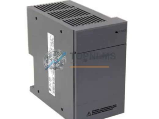
Allen-Bradley 1746-P5 Ruggedized DC Power Supply Module
1746-P5Allen-Bradley 1746-P5 ruggedized DC power supply for SLC 500 PLC. Harsh environment rated, 12-month warranty, tested stock. Fast global shipping from TOPNLMS.
Request availability, condition, lead time and export shipping details for 142129 135232-04.
Send this exact part number, quantity and destination country. TOPNLMS will confirm availability, condition and export lead time before quotation.
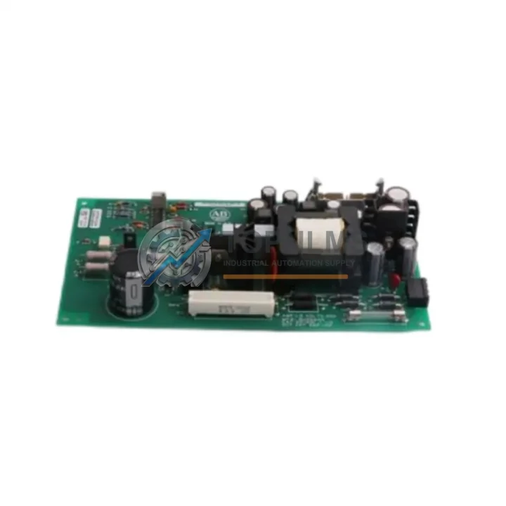
The Allen-Bradley 142129 / 135232-04 Power Supply Board is a critical component in legacy Rockwell Automation control architectures. As industrial facilities continue to modernize aging PLC-5 and SLC 500 control systems, sourcing a verified, tested replacement for this discontinued power supply board has become a top priority for maintenance engineers and procurement teams worldwide. TOPNLMS stocks this unit ready for immediate dispatch, enabling you to minimize unplanned downtime and execute a controlled, low-risk upgrade or emergency swap without compromising your production schedule.
Whether you are performing a like-for-like emergency replacement, executing a phased migration from a PLC-5 rack to a ControlLogix platform, or consolidating spare parts inventory ahead of a planned shutdown, the 142129 / 135232-04 is a direct-fit solution that eliminates the need for immediate full-system re-engineering. This board maintains the original backplane power distribution architecture, ensuring that existing I/O modules, communication adapters, and processor cards seated in the same rack continue to operate without modification to field wiring or control logic.
| Parameter | Original: 142129 / 135232-04 | Replacement Unit (This Listing) |
|---|---|---|
| Part Number | 142129 / 135232-04 | 142129 / 135232-04 (OEM equivalent) |
| Brand / Manufacturer | Allen-Bradley / Rockwell Automation | Allen-Bradley / Rockwell Automation |
| Compatible Platform | PLC-5 Series, SLC 500 Series Rack | PLC-5 Series, SLC 500 Series Rack |
| Backplane Interface | Standard Allen-Bradley backplane connector | Direct-fit, no adapter required |
| Output Voltage | +5 VDC / +24 VDC (rack-dependent) | Matched to original specification |
| Installation Requirement | Slot 0 / dedicated PSU slot in rack | Same slot position, no mechanical modification |
| Field Wiring Impact | N/A (internal board) | Zero — no field wiring changes required |
| Communication Protocol Compatibility | DH+, DH-485, ControlNet (rack-level) | Fully compatible — no protocol reconfiguration |
| Replacement Category | Discontinued / End-of-Life (EOL) | Direct replacement, in-stock |
| Warranty | OEM warranty expired | 12-Month TOPNLMS Warranty |
A power supply board replacement rarely occurs in isolation. In most PLC-5 and SLC 500 migration projects, the 142129 / 135232-04 is replaced alongside a broader set of components to restore full system integrity or to stage a controlled platform upgrade. During the retrofit process, engineers commonly address the processor module — such as the 1785-L40B or 1785-L80B PLC-5 processor — to verify firmware compatibility and ensure the CPU continues to communicate correctly with the refreshed power rail. In parallel, the 1746-A13 or 1746-A7 SLC 500 rack chassis may be inspected for backplane connector wear, particularly when the power supply board has failed due to sustained overload or thermal stress.
Communication continuity is another key concern during migration. The 1785-KA5 Data Highway Plus (DH+) communication adapter and the 1747-SDN DeviceNet Scanner module are frequently retained from the original system and must be verified for compatibility with the replacement power supply’s output stability. Where the facility is transitioning toward an Ethernet/IP architecture, the 1756-ENBT ControlLogix Ethernet/IP bridge module is often introduced at this stage, requiring careful attention to rack power budgeting to ensure the new supply can support the additional communication load.
On the I/O side, the 1746-IB16 digital input module and 1746-OB16 digital output module are standard SLC 500 components that remain in service during a power supply swap, provided the replacement board delivers a stable +5 VDC backplane voltage within specification. For analog signal chains, the 1746-NI4 analog input module requires particular attention to power quality, as voltage ripple on the backplane can introduce measurement errors in precision process control loops. Ensuring the replacement 142129 / 135232-04 board passes pre-installation load testing is therefore a recommended commissioning step before returning the system to production.
Where the migration scope extends to the operator interface layer, the 2711-T10C20 PanelView 1000 HMI terminal — commonly paired with PLC-5 systems via DH+ — should be verified for communication continuity after the power supply replacement, as any interruption to the DH+ network during the swap may require a terminal restart and communication parameter re-confirmation. Finally, for facilities managing the transition to a ControlLogix 1756 platform in parallel, the 1756-PA75 ControlLogix power supply module represents the target-state equivalent, and procurement teams often source both units simultaneously to support a staged cutover strategy.
Q: Do I need to modify field wiring when replacing the 142129 / 135232-04?
A: No. This is an internal backplane power supply board. All field wiring terminates at I/O modules, not at the power supply board itself. Replacement requires only the removal of the failed board and insertion of the replacement unit into the same slot position.
Q: Will my existing PLC-5 or SLC 500 program need to be reloaded after the swap?
A: No. The control program resides in the processor module’s battery-backed RAM or flash memory, not in the power supply board. Provided the processor battery is healthy and the system is powered down correctly before the swap, the program will be retained. A full program backup prior to any maintenance operation is always recommended.
Q: Is the DH+ or DH-485 communication network affected during the replacement?
A: The communication network will be interrupted during the power-down period required for the swap. Once the replacement board is installed and the rack is powered up, DH+ and DH-485 communication resumes automatically without reconfiguration, as the network parameters are stored in the communication adapter modules, not in the power supply.
Q: What is the physical installation space requirement?
A: The 142129 / 135232-04 occupies the dedicated power supply slot in the Allen-Bradley rack. No additional panel space or DIN rail mounting is required. The replacement board is dimensionally identical to the original, ensuring a direct mechanical fit without modification to the control cabinet layout.
Q: Can this board be used in a mixed I/O rack with both digital and analog modules?
A: Yes. The board provides the standard backplane power distribution required for both digital and analog I/O modules. For racks with a high proportion of analog modules, verify the total rack power budget against the board’s rated output current to ensure adequate headroom.
Q: What commissioning steps are recommended after installation?
A: After installation, power up the rack and verify the power supply status LED indicates normal operation. Confirm that all I/O module status LEDs are active and that the processor module has resumed normal scan cycle operation. For systems with DH+ communication, verify that all network nodes are visible in the RSLinx Classic node browser before returning the system to automatic mode.
Every Allen-Bradley 142129 / 135232-04 Power Supply Board shipped by TOPNLMS is covered by a 12-Month Warranty from the date of delivery. Prior to dispatch, each unit undergoes a functional load test to verify output voltage stability, backplane connector integrity, and thermal performance under rated conditions. Units that do not meet original Allen-Bradley specification tolerances are quarantined and not offered for sale.
In the event of a warranty claim, TOPNLMS provides a direct replacement unit or full refund, subject to inspection of the returned item. Our average response time for warranty inquiries is within one business day. Replacement units for confirmed warranty cases are dispatched within 3–5 business days from claim approval.
For procurement teams managing critical spare parts programs, TOPNLMS can provide batch testing documentation, individual unit serial number records, and pre-shipment inspection reports upon request. We ship globally from Xiamen, China, with DHL Express, FedEx International Priority, and UPS Worldwide Expedited available as standard shipping options to minimize lead time for urgent replacement requirements.
For volume orders, framework agreements, or technical pre-sales consultation, contact our industrial automation team directly.
Allen-Bradley 1746-P5 ruggedized DC power supply for SLC 500 PLC. Harsh environment rated, 12-month warranty, tested stock. Fast global shipping from TOPNLMS.
Allen-Bradley 1606-XLS240EA 240W 24VDC DIN-Rail power supply. Ruggedized for harsh environments. 12-month warranty, tested, fast ship. Buy at TOPNLMS.
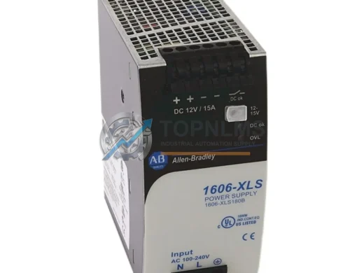
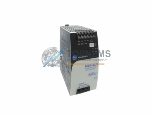
Buy Allen-Bradley 1606-XLS120E original industrial spare. 120W 24VDC DIN-Rail power supply, 1606-XLS Series compatible. 12-month warranty. Fast shipping from TOPNLMS.
Allen-Bradley 1606-XL60D: 24VDC 60W ruggedized DIN-rail power supply for harsh industrial environments. In stock, tested, 12-month warranty. Ships fast.
Click Quote This Model and the Part Number field will auto-fill with 142129 135232-04.