Product Overview
Allen-Bradley 1336-PB-SP8C Upgrade Solution for 1336 PLUS II: Smooth Migration from Legacy AC Drive Systems
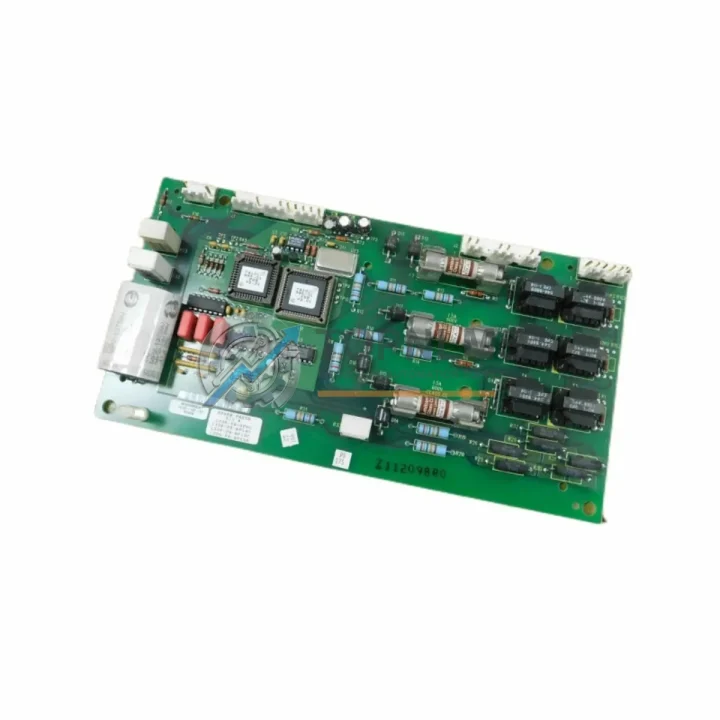
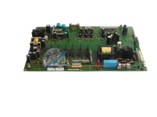
The Allen-Bradley 1336-PB-SP8C is the dedicated power control board for the Rockwell Automation 1336 PLUS and 1336 PLUS II series AC variable frequency drives. As these drives reach or exceed their end-of-life support window, industrial facilities running legacy conveyor systems, pump stations, HVAC air handlers, compressor lines, and motor control centers face an urgent need for a reliable, drop-in replacement that eliminates extended downtime and costly full-drive changeouts.
TOPNLMS supplies tested, ready-to-ship 1336-PB-SP8C power control boards — along with its interchangeable variants 1336-PB-SP14C, 1336-PB-SP19C, and 1336-PB-SP23A (OEM reference 74101-181-51) — sourced from verified industrial channels. Each unit undergoes functional verification prior to dispatch, ensuring your maintenance team receives a board that is ready for immediate installation without the uncertainty of untested surplus stock.
Compatibility Comparison Table
| Parameter |
Legacy / Replaced Part |
Replacement Board (This Unit) |
| Part Numbers |
1336-PB-SP8C, 1336-PB-SP14C, 1336-PB-SP19C, 1336-PB-SP23A |
1336-PB-SP8C / SP14C / SP19C / SP23A (OEM: 74101-181-51) |
| Compatible Drive Series |
1336 PLUS (Series A/B), 1336 PLUS II (Series A/B/C) |
1336 PLUS & 1336 PLUS II — all frame sizes covered by SP8C–SP23A |
| Drive Frame / Power Range |
SP8C: up to 8A; SP14C: up to 14A; SP19C: up to 19A; SP23A: up to 23A output current |
Matched to original frame — confirm nameplate current rating before ordering |
| Mounting & Form Factor |
Direct board-level replacement; same PCB footprint and connector positions |
Drop-in fit — no chassis modification required |
| Interface / Connectors |
Internal ribbon and power harness connectors per 1336 PLUS II architecture |
Identical connector layout; no re-pinning or adapter required |
| Communication Protocol |
Works alongside 1336-GM1 (DH+), 1336-GM2 (Remote I/O), 1336-GM3 (DeviceNet) option cards |
Full compatibility retained — existing comms option cards remain in place |
| Control Wiring |
Existing TB1/TB2 terminal block wiring unchanged |
No rewiring required; existing field wiring reused directly |
| Programming / Parameters |
Drive parameters stored in 1336-MOD-L10 or 1336-MOD-L20 memory module |
Parameter memory module transfers intact — no reprogramming needed if module is retained |
| Installation Space |
Standard 1336 PLUS II enclosure — no additional panel space required |
Same board dimensions; fits existing drive chassis without modification |
| Warranty |
OEM support discontinued / EOL |
12-Month Warranty from TOPNLMS — replacement or refund on verified defects |
Seamless Upgrade Solutions
A successful 1336 PLUS II power control board replacement rarely involves a single component in isolation. During the retrofit process, maintenance engineers typically audit the surrounding drive architecture to prevent repeat failures and ensure the upgraded system operates reliably for the next service cycle.
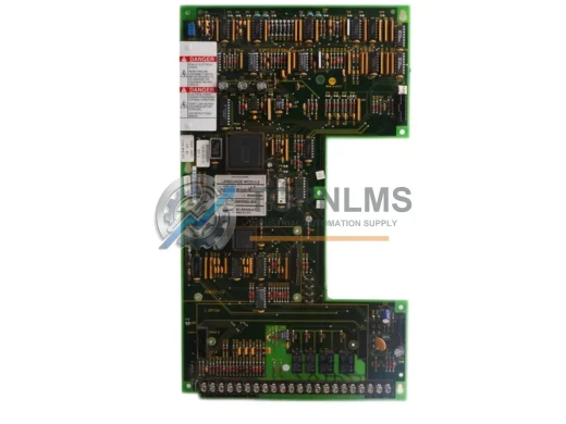
When replacing the 1336-PB-SP8C board, it is common practice to simultaneously inspect and, where necessary, replace the 1336-PB-SP2A gate driver board, which interfaces directly with the IGBT power module and is subject to similar thermal stress cycles. If the drive’s DC bus capacitor bank shows signs of bulging or elevated ESR, the 1336-PB-SP1A capacitor assembly should be addressed in the same maintenance window to avoid a secondary failure shortly after the board swap.
For facilities that rely on network-integrated motor control, the 1336-GM3 DeviceNet communication option card or the 1336-GM2 Remote I/O adapter should be verified for firmware compatibility with the replacement board. These option cards plug into the drive’s option card slot and do not require removal during the power board exchange, but their status LEDs should be confirmed post-commissioning.
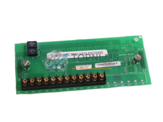
If the drive is connected to a 1336-MOD-L10 or 1336-MOD-L20 parameter memory module, the module should be removed before board extraction and reinserted after the new board is seated. This preserves all tuned parameters — acceleration ramps, current limits, PID setpoints — eliminating the need for a full recommissioning cycle on the motor load.
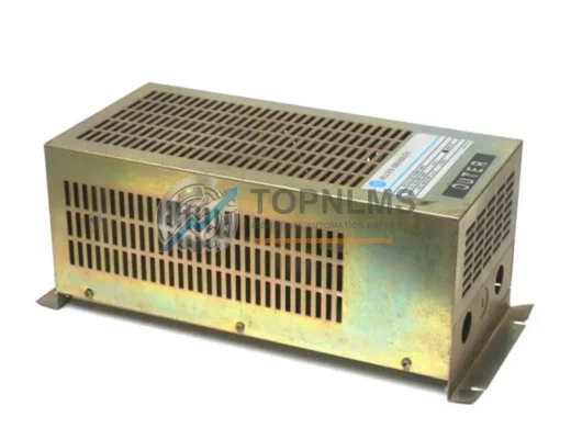
Facilities migrating from older 1336 PLUS (non-PLUS II) frames to PLUS II architecture may also need to evaluate the 1336-PB-SP5A precharge board and the 1336-L5E or 1336-L10E line filter module to ensure EMC compliance is maintained after the upgrade. In control cabinet environments where multiple drives share a common DC bus or a shared 24 VDC control power supply, the 1336-PB-SP3A power supply board should be load-tested to confirm it can support the restored drive without voltage droop.
For sites using a PanelView 550 or PanelView 900 HMI connected via DH+ to the 1336 PLUS II drive, no HMI reconfiguration is required following a board-level replacement, provided the 1336-GM1 DH+ option card and node address settings are preserved. The HMI will resume communication automatically once the drive completes its power-on self-test sequence.
In applications where the 1336 PLUS II drives a critical pump or compressor with a 1336-BDB-SP2 dynamic braking module, the braking resistor wiring and thermal cutout should be inspected during the same service visit. Braking module faults are a common secondary symptom of power board degradation and are easily overlooked until the drive is returned to full-load operation.
Retrofit Guidance FAQ
Q: Can I reuse my existing field wiring when replacing the 1336-PB-SP8C?
A: Yes. The terminal block layout on the 1336 PLUS II control board is identical across SP8C, SP14C, SP19C, and SP23A variants. All existing TB1 and TB2 field wiring — including analog reference inputs, digital I/O, and fault relay connections — can be reconnected to the same terminal positions without modification.
Q: Will I need to reprogram the drive after the board swap?
A: Not if you retain the 1336-MOD-L10 or 1336-MOD-L20 parameter memory module. Remove the module before extracting the faulty board, install the replacement board, then reinsert the module. The drive will load all stored parameters on the next power cycle. If no memory module is present, parameters will need to be re-entered manually using a 1336-DNET-ENI or directly via the integral keypad.
Q: Is the 1336-PB-SP8C compatible with both 1336 PLUS and 1336 PLUS II drives?
A: The SP8C, SP14C, SP19C, and SP23A designations apply to the 1336 PLUS II series. While some early 1336 PLUS (Series B) frames share similar board architecture, always verify the drive nameplate and catalog number before ordering to confirm the correct variant for your specific frame size and output current rating.
Q: What communication protocols are supported after the board replacement?
A: The power control board replacement does not affect the drive’s communication capability. All existing option cards — DH+ (1336-GM1), Remote I/O (1336-GM2), DeviceNet (1336-GM3), and ControlNet (1336-GM6) — remain fully functional. Node addresses and baud rate settings are stored in the drive’s non-volatile memory and are unaffected by the board swap.
Q: Does the replacement board fit the existing drive chassis without modification?
A: Yes. The 1336-PB-SP8C replacement board is a direct PCB-level replacement with identical mounting hole positions, connector locations, and board dimensions. No chassis drilling, bracket modification, or adapter plate is required. Installation time is typically 30–60 minutes for a technician familiar with the 1336 PLUS II drive architecture.
Q: How do I verify the board is functioning correctly after installation?
A: After installation, power up the drive with no load connected and confirm the keypad or HMI displays the correct drive status (Ready). Check that all status LEDs on the control board and any installed option cards are in their normal states. Run the drive at low speed (5–10 Hz) with the motor connected and verify output current readings on all three phases before returning the system to full production load.
Warranty Assurance
Every 1336-PB-SP8C, 1336-PB-SP14C, 1336-PB-SP19C, and 1336-PB-SP23A power control board shipped by TOPNLMS is covered by a 12-Month Warranty from the date of delivery. Our warranty commitment covers verified manufacturing defects and functional failures under normal operating conditions.
- Pre-shipment Testing: Each board is functionally verified before dispatch. We do not ship untested surplus stock.
- Replacement Support: In the event of a warranty claim, TOPNLMS will arrange a replacement unit or issue a refund upon confirmation of the defect. Our technical team will guide you through the return and replacement process to minimize your downtime.
- Fast Dispatch: In-stock units are dispatched within 1–3 business days from our Xiamen warehouse. Express shipping options are available for urgent breakdown situations.
- After-Sales Response: Our industrial parts team responds to warranty inquiries and technical questions within 24 hours on business days. Contact us at [email protected] or +86 18359293191.
- Procurement Assurance: We provide commercial invoices, packing lists, and test reports upon request to support your procurement and quality documentation requirements.
TOPNLMS is committed to supporting industrial facilities through legacy system maintenance, planned upgrades, and emergency breakdown recovery. Whether you need a single board for an urgent repair or a standing stock arrangement for ongoing maintenance, our team is ready to assist.