Product Overview
ABB SDCS-PIN-4 3ADT314100R1001 DCS800 Replacement: Seamless Transition from Legacy DC Drive Systems
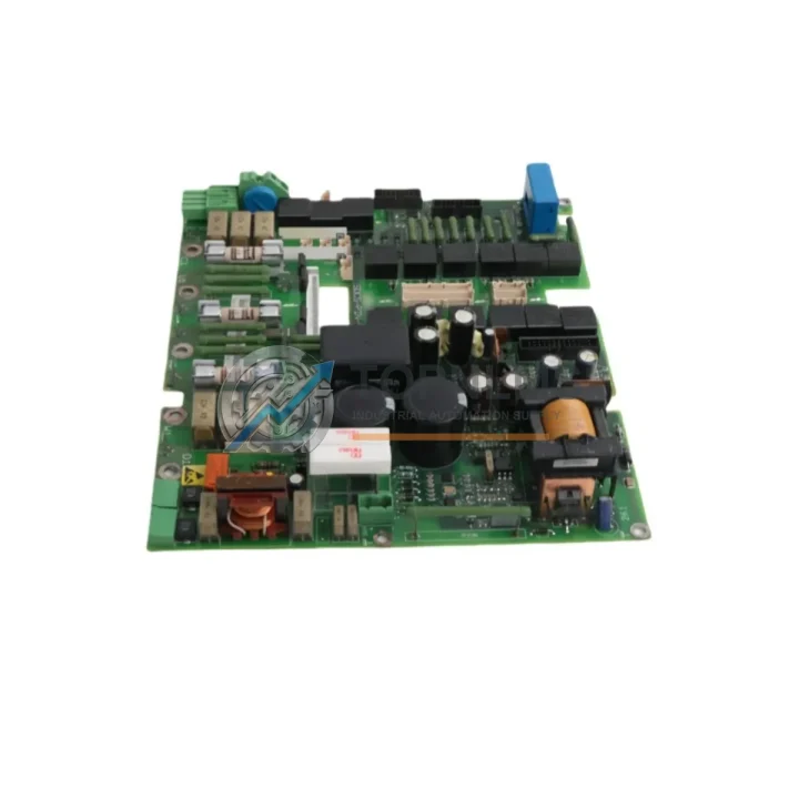
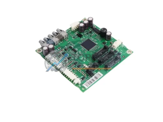
The ABB SDCS-PIN-4 (part number 3ADT314100R1001) is the Power Interface Board at the heart of the ABB DCS800 series DC drive platform. As aging DCS400, DCS500, and earlier DCS600 installations reach end-of-service life, plant engineers and procurement teams are actively seeking verified replacement boards that allow a smooth, low-risk migration without full drive cabinet redesign. The SDCS-PIN-4 serves as the critical bridge between the drive’s power electronics and its control intelligence, managing gate firing signals, DC bus voltage feedback, and current measurement loops that are fundamental to precise motor speed and torque regulation.
When the original SDCS-PIN-4 fails or becomes unavailable through standard OEM channels, the consequences are immediate: unplanned downtime, halted production lines, and costly emergency procurement. Our verified stock of the SDCS-PIN-4 3ADT314100R1001 is sourced from authorized distribution channels and subjected to functional pre-shipment testing, ensuring that the board you receive is ready for direct installation into your DCS800 drive frame.
Compatibility Comparison Table
| Parameter |
Legacy / Predecessor |
SDCS-PIN-4 3ADT314100R1001 |
| Drive Platform |
DCS400 / DCS500B / DCS600 |
ABB DCS800 Series |
| Board Function |
Power Interface / Gate Driver |
Power Interface Board (PIN) |
| Connector Interface |
Varies by predecessor model |
DCS800 standard backplane connector |
| DC Bus Voltage Feedback |
Analog signal conditioning |
Integrated precision voltage sensing |
| Current Measurement |
External shunt / CT required |
On-board current transducer interface |
| Gate Firing Signals |
Discrete optocoupler outputs |
Integrated fiber-optic gate drive |
| Communication Protocol |
Proprietary / DDCS |
DDCS / PROFIBUS / Modbus RTU compatible via SDCS-COM modules |
| Installation Space |
Frame-specific mounting |
DCS800 standard frame slot (D1–D7) |
| Supply Voltage |
24 VDC auxiliary |
24 VDC auxiliary (SDCS-POW-4 compatible) |
| Replacement Recommendation |
Direct board swap within DCS800 frame |
✔ Drop-in replacement, no rewiring required |
| Warranty |
— |
12-Month Warranty from shipment date |
Seamless Upgrade Solutions
A successful SDCS-PIN-4 replacement rarely happens in isolation. In most DCS800 retrofit projects, the power interface board is replaced as part of a broader drive modernization effort. During commissioning, engineers frequently find that adjacent components also require attention to restore full system integrity.
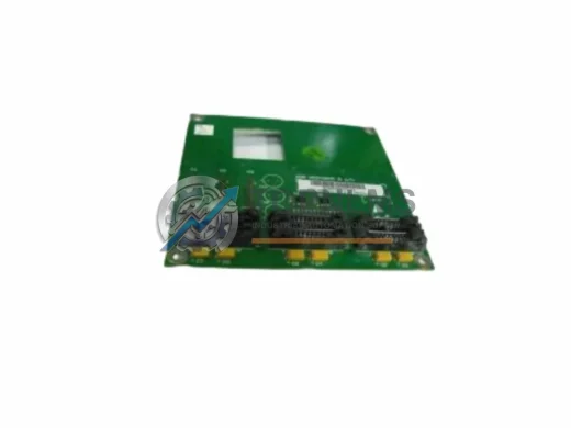
The SDCS-CON-F (Control Board) works in direct coordination with the SDCS-PIN-4, handling the closed-loop speed and current regulation algorithms. If the control board firmware is outdated or the board itself shows signs of capacitor aging, replacing both the SDCS-PIN-4 and the SDCS-CON-F simultaneously eliminates the risk of a second unplanned outage within months of the initial repair. Similarly, the SDCS-POW-4 auxiliary power supply board provides the 24 VDC rail that feeds both the control and interface boards; a degraded SDCS-POW-4 is a common root cause of intermittent SDCS-PIN-4 faults and should be inspected during any board-level replacement.
For sites migrating from older DCS500B or DCS600 installations, the physical drive cabinet may need to accommodate the DCS800 frame dimensions. In these cases, the SDCS-DSL-4 (Drive Slot Adapter) and appropriate DCS800 mounting frames allow the new drive assembly to occupy the same cabinet footprint as the legacy unit, preserving existing cable routing and minimizing civil works. The SDCS-FEX-2 field excitation module is another component that frequently accompanies DCS800 upgrades in separately excited DC motor applications, ensuring that the excitation control loop is matched to the new drive’s regulation architecture.
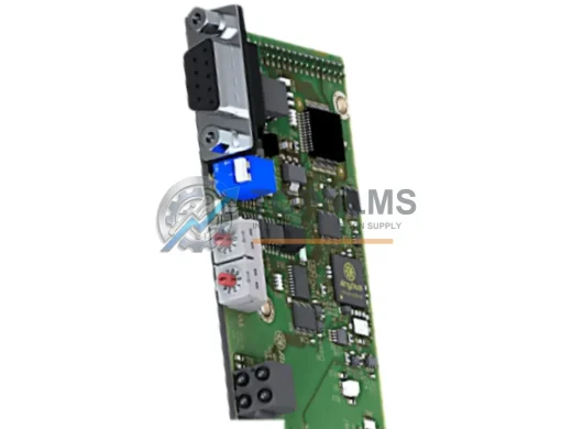
On the communications side, many legacy DC drive installations relied on hardwired analog speed references and discrete I/O for start/stop commands. Modern plant networks increasingly demand PROFIBUS DP or Modbus RTU integration. The SDCS-COM-8 (PROFIBUS adapter) and SDCS-COM-5 (DeviceNet adapter) plug directly into the DCS800 option slot and allow the drive to participate in the plant’s existing fieldbus topology without additional signal converters or PLC I/O expansion. For sites already running ABB’s DDCS fiber-optic network, the NDBU-95 branching unit and RDCO-03 DDCS communication module provide the high-speed drive-to-controller link that supports multi-drive coordination in winder, extruder, and paper machine applications.
Terminal wiring compatibility is a practical concern that often determines project schedule. The DCS800’s standard I/O terminal block layout is designed to accept the same 24 VDC digital input signals and ±10 V analog references used by the DCS500B, meaning that existing field wiring can typically be reconnected without modification. Where signal isolation is required between the drive and a legacy PLC rack, a DIN-rail mounted signal isolator (such as a Phoenix Contact MINI MCR or equivalent) can be inserted inline without affecting the drive’s control loop performance.
Retrofit Guidance FAQ
Q: Can I replace only the SDCS-PIN-4 without replacing the SDCS-CON-F control board?
A: Yes, in most cases the SDCS-PIN-4 can be replaced independently. However, if the control board firmware version is below the minimum compatible release for the replacement PIN board revision, a firmware update via the DriveWindow Light tool may be required before commissioning.
Q: Will existing field wiring need to be modified?
A: For like-for-like DCS800 frame replacements, no rewiring is required. The SDCS-PIN-4 uses the same backplane connector and the same external power terminal positions as the original board. For migrations from DCS500B or DCS600, terminal mapping should be verified against the DCS800 hardware manual (3ADW000379) before reconnection.
Q: Is the SDCS-PIN-4 compatible with PROFIBUS and Modbus RTU?
A: The SDCS-PIN-4 itself handles power-stage interfacing; fieldbus communication is managed by the SDCS-COM option board installed in the DCS800’s communication slot. The SDCS-PIN-4 replacement does not affect the existing SDCS-COM-8 (PROFIBUS) or SDCS-COM-5 (DeviceNet) configuration.
Q: How much physical space does the DCS800 require compared to the DCS500B?
A: DCS800 frame sizes D1 through D4 have a similar footprint to DCS500B frames B1–B4. Frame D5 and above may require cabinet depth adjustment. Detailed dimensional drawings are available in the DCS800 Hardware Manual.
Q: What is the recommended procedure for on-site commissioning after board replacement?
A: After installing the SDCS-PIN-4, perform a visual inspection of all connector seating, verify auxiliary supply voltage at the SDCS-POW-4 output, and run the drive’s auto-tuning routine via the CDP312R control panel or DriveWindow to re-establish current controller parameters. Log all fault codes before and after replacement for maintenance records.
Q: Can the SDCS-PIN-4 be used in a redundant drive configuration?
A: Yes. In multi-drive systems using the DDCS fiber-optic network with an NDBU-95 branching unit, the SDCS-PIN-4 replacement board participates in the same master-follower topology as the original, provided the DDCS node address is correctly set on the SDCS-CON-F control board.
Warranty Assurance
Every SDCS-PIN-4 3ADT314100R1001 shipped by TOPNLMS is covered by a 12-month warranty from the date of shipment. Our pre-shipment testing protocol includes functional power-up verification, gate signal output checks, and visual inspection for component damage, corrosion, or counterfeit indicators. Boards that do not pass all test criteria are quarantined and never shipped.
In the event of a warranty claim, our after-sales team responds within 24 business hours. Replacement boards are dispatched from our Xiamen warehouse via DHL Express or FedEx International Priority, with typical transit times of 3–7 business days to most industrial regions in Europe, Southeast Asia, and the Americas. We maintain buffer stock of the SDCS-PIN-4 and related DCS800 spare parts to support emergency procurement requests with same-day or next-day dispatch.
For procurement teams requiring documentation, we provide a test report, packing list, and commercial invoice with each shipment. HS code classification and country-of-origin certificates (Germany) are available on request to support customs clearance in regulated markets.
To place an order, request a quotation, or verify stock availability, contact our technical sales team directly.